
Summary of Cat Repelling PIR motion sensor (covert) speaker box alarm using Arduino
This article details a DIY project to build a covert, speaker-shaped motion sensor device using an Arduino Uno. Designed to deter the author's cat from knocking items off a dresser at 4 AM, the device detects movement via a PIR sensor and triggers a piezo buzzer to play repelling noises. The project involves programming the Arduino, wiring the electronic components, and constructing a custom wooden case painted black to blend in as a speaker.
Parts used in Cat Repelling Motion Sensor:
- Arduino Uno
- 9V battery
- 9V battery clip
- 2.1mm power plug
- Various lengths of wire
- PIR motion sensor
- Piezo buzzer alarm (9V or lower)
- LED
- Heat Shrink Tubing
- Solder
- USB cable (to arduino)
- Soldering Iron
- Wire clippers
- Paneling
- Plywood
- Phillips Panhead screws - 1/4" (2)
- Phillips Panhead screws - 1/2" (4)
- Hot Glue
- Interior Construction Adhesive
- Black Pantyhose
- Primer
- Black paint (flat)
- Power saw
- Ruler
- Dremel Tool
- Drill (with various bits)
This is a PIR motion sensor device that works with the arduino uno. In order to make it covert enough to be placed in multiple settings and portable enough to fit most places, I decided to make the case for it appear as a speaker.
The inspiration for this project:
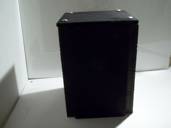
My cat is a jerk. One of his favorite things to do is to alarm me that he is hungry every morning at 4am by sitting on my dresser and knocking random things over until I wake up. Unfortunately, my dresser is also parallel to my craft table, so he has turned my dresser into a work of art by walking across my oil paintings and jumping up there (and also throughout the rest of the house). I could lock him out of my room, but then he cries outside the door all night, so I’ve been trying to come up with a solution to this problem.
After looking through Instructables and finding out what is possible with the arduino, I decided to make a motion sensing device for my dresser that will play cat repelling noises until Mr. Moe is trained out of his annoying behavior.
Step 1: Materials you will need:
The Motion Sensor:
Arduino Uno
9V battery9
V battery clip
2.1mm power plug
Various lengths of wire
PIR motion sensor
Piezo buzzer alarm (9V or lower)
LED
Heat Shrink Tubing
Solder
USB cable (to arduino)
Tools for Motion Sensor:
Soldering Iron
Wire clippers
The Speaker Case:
Paneling
Plywood
Phillips Panhead screws – 1/4″ (2)
Phillips Panhead screws – 1/2″ (4)
Hot Glue
Interior Construction Adhesive
Black Pantyhose
Primer
Black paint (flat)
Tools for Speaker Case:
Power saw
Ruler
Dremel Tool
Drill (with various bits)
Step 2: Program the Arduino:
The first thing that you should do is to upload the motion sensor code to your arduino.
I found a good code here: http://make-documents.s3.amazonaws.com/fv1fYSLfy6QRgANM.pdf
Open the pdf and copy the code into a new sketch in the arudino program.
I found one small error in the code where a comment stating ” numbers 10, 11)” ran into the program. Just delete this or cut and paste it in it’s proper place right above the line.
Compile, and then plug in the arudino with the USB cable and upload it.
Next you can begin to construct your motion sensor circut.
Step 3: Attach the PIR Sensor:
First you will connect the arduino to the PIR motion sensor. Gather your wires and cut three to about 6 inches and strip the ends so that they can easily be plugged into the slots of the arduino. I recommend using wires of different color or shrink tubing to make things easier to remember.
Once your wires are cut, you will need to solder your wires to your PIR sensor.
The wires with the tubing in the picture (black, red, and yellow) are the wires I attached to my PIR.
Wire 1: Plug into the second GND slot in the arduino and twist the opposite end of the wire to the GND peg of the PIR. (black in the picture)
Wire 2: 5v slot of the arduino to VCC of the PIR. (red in the picture)
Wire 3: Slot 2 to of the arduino to OUT peg in PIR. (yellow in the picture)
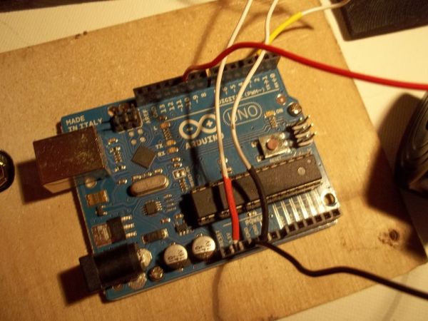
WARNING: Do not connect VCC to VIN. I burned out my arduino this way.
Step 4: Attach your Piezo Buzzer:
Now you are ready to hook up your piezo buzzer.
Most piezo buzzers have wires attached to them: the black wire goes to GND and the red wire to pin 10. If yours doesn’t, don’t worry. The polarity in this case isn’t integral.
(In the picture the buzzer’s wires are solid black and solid red)
Arduino Uno
9V battery9
V battery clip
2.1mm power plug
Various lengths of wire
PIR motion sensor
Piezo buzzer alarm (9V or lower)
LED
Heat Shrink Tubing
Solder
USB cable (to arduino)
Tools for Motion Sensor:
Soldering Iron
Wire clippers
The Speaker Case:
Paneling
Plywood
Phillips Panhead screws – 1/4″ (2)
Phillips Panhead screws – 1/2″ (4)
Hot Glue
Interior Construction Adhesive
Black Pantyhose
Primer
Black paint (flat)
Tools for Speaker Case:
Power saw
Ruler
Dremel Tool
Drill (with various bits)
For more detail: Cat Repelling PIR motion sensor (covert) speaker box alarm using Arduino
-
What is the main purpose of this project?
To create a motion sensing device that plays cat repelling noises to stop a cat from knocking things off a dresser. -
How can the device be made to look like a speaker?
By constructing a case using paneling, plywood, primer, and black flat paint to appear as a speaker. -
Which pins on the Arduino connect to the PIR sensor?
GND connects to GND, 5v connects to VCC, and Slot 2 connects to the OUT peg. -
What warning is given regarding the PIR sensor connection?
Do not connect VCC to VIN, as this will burn out the Arduino. -
Where should the piezo buzzer wires be connected?
The black wire goes to GND and the red wire goes to pin 10. -
Can the polarity of the piezo buzzer wires be reversed?
Yes, the polarity is not integral for this specific setup. -
What tool is recommended to make wire connections easier to identify?
Using wires of different colors or heat shrink tubing. -
How do you handle the code error mentioned in the instructions?
Delete the comment stating numbers 10, 11) or cut and paste it above the proper line.
