
Summary of Button State Change Detection using Arduino
Once you have a pushbutton, you can detect when it changes from OFF to ON (edge detection) by comparing its current reading to the previous reading and incrementing a counter when an OFF-to-ON transition occurs. A pull-down resistor prevents floating inputs. The sketch counts button presses and lights the LED on pin 13 whenever the count is a multiple of four.
Parts used in the State change detection using Arduino:
- Arduino Board
- Momentary button or switch
- 10K ohm resistor
- Breadboard
- Hook-up wire
- LED on pin 13 (Arduino built-in or external)
Once you’ve got a pushbutton working, you often want to do some action based on how many times the button is pushed. To do this, you need to know when the button changes state from off to on, and count how many times this change of state happens. This is called state change detection or edge detection.
Circuit
image developed using Fritzing. For more circuit examples, see the Fritzing project page
Connect three wires to the Arduino board. The first goes from one leg of the pushbutton through a pull-down resistor (here 10 KOhms) to ground. The second goes from the corresponding leg of the pushbutton to the 5 volt supply. The third connects to a digital i/o pin (here pin 2) which reads the button’s state.
When the pushbutton is open (unpressed) there is no connection between the two legs of the pushbutton, so the pin is connected to ground (through the pull-down resistor) and we read a LOW. When the button is closed (pressed), it makes a connection between its two legs, connecting the pin to voltage, so that we read a HIGH. (The pin is still connected to ground, but the resistor resists the flow of current, so the path of least resistance is to +5V.)
If you disconnect the digital i/o pin from everything, the LED may blink erratically. This is because the input is “floating” – that is, not connected to either voltage or ground. It will more or less randomly return either HIGH or LOW. That’s why you need a pull-down resistor in the circuit.
Schematic
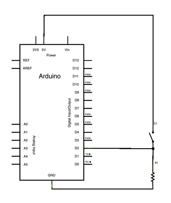
The sketch below continually reads the button’s state. It then compares the button’s state to its state the last time through the main loop. If the current button state is different from the last button state and the current button state is high, then the button changed from off to on. The sketch then increments a button push counter.
The sketch also checks the button push counter’s value, and if it’s an even multiple of four, it turns the LED on pin 13 ON. Otherwise, it turns it off.
Code
State change detection (edge detection)Often, you don’t need to know the state of a digital input all the time,
but you just need to know when the input changes from one state to another.
For example, you want to know when a button goes from OFF to ON. This is called
state change detection, or edge detection.
Hardware Required
- Arduino Board
- momentary button or switch
- 10K ohm resistor
- breadboard
- hook-up wire
- How is the pushbutton wired to detect state changes?
One leg of the pushbutton goes to 5V, the corresponding leg goes to the digital input pin, and that pin is connected through a 10K pull-down resistor to ground. - Why is a pull-down resistor needed?
To prevent the input from floating and randomly reading HIGH or LOW when the pin is disconnected. - How does the sketch detect an OFF-to-ON transition?
The sketch reads the current button state, compares it to the last state, and if they differ and the current state is HIGH, it counts a button push. - What happens when the button push counter is a multiple of four?
The sketch turns the LED on pin 13 ON when the counter is an even multiple of four; otherwise it turns it off. - What does the input read when the button is unpressed?
When unpressed, the pin is connected to ground through the pull-down resistor and reads LOW. - What does the input read when the button is pressed?
When pressed, the button connects the pin to +5V and the input reads HIGH. - What causes erratic LED blinking if the pin is disconnected?
Erratic blinking is caused by the input floating when it is not connected to either voltage or ground. - Which Arduino pin is used in the example for reading the button?
The example uses digital pin 2 to read the button state.
