Summary of Build Your FM Transmission Station With Arduino
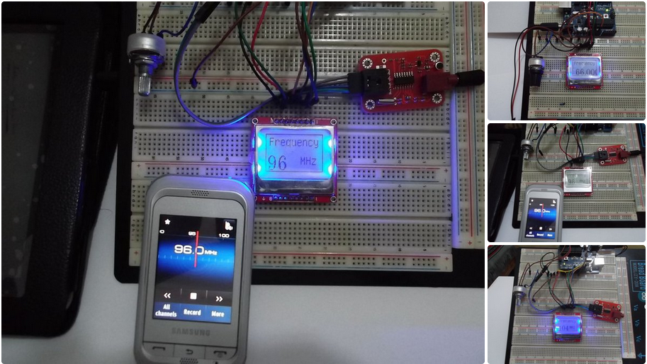
This article details a DIY FM transmitter project that broadcasts audio from a computer to standard radios. The system uses an Arduino Uno to control an ElecHouse FM module and displays the frequency on a Nokia 5110 LCD screen. Users can adjust the transmission frequency using a potentiometer, with the range set to 87-108 MHz for the USA region.
Parts used in the Simple FM Transmitter:
- Arduino Board (Uno R3)
- LCD Nokia 5110 PCD8544
- FM Transmitter module V1.0 ElecHouse
- Solderless Jumper Male-Male
- BreadBoard
- Potentiometer (50K ohm and 500 Ohm)
- Battery 9V With Holder
Hi every body .
Before A 3 months Ago , one of my friend ask me to build a Simple FM transmitter , he Would to transmit An Audio File from computer and PLAY it on any radio channel , By adjust the frequency of receiver as same as transmitter frequency

I searched on the internet on for this circuit , But I don’t find my target .
There were some circuits with many component , or with miss component , so I search more and i Found one of the amazing method, effective and easy to use , with few component .
and for easy interface with , I added A graphical LCD Nokia 5110 PCD8544 , and added a Potentiometer to tune the transmitter Frequency .
let’s see what we need :
Step 1: Material

At first , I connect all part’s on BreadBoard , and i design will PCB For it soon .
The component we need for this device :
1)Arduino Board , Uno for example.
http://www.ebay.com/itm/Original-Genuine-Arduino-Uno-R3-Board-New-in-box-from-Italy-/271207670126?pt=LH_DefaultDomain_2&hash=item3f253ca16e
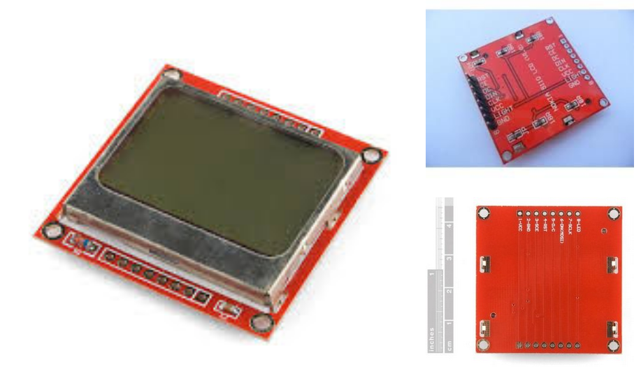
2) LCD Nokia 5110 PCD8544
http://www.ebay.com/itm/1pcs-84-48-LCD-Module-White-backlight-adapter-pcb-for-Nokia-5110-/400347868649?pt=LH_DefaultDomain_0&hash=item5d3697ade9
3)FM Transmitter module V1.0 ElecHouse
http://www.ebay.com/itm/140878623449?ssPageName=STRK:MEWNX:IT&_trksid=p3984.m1439.l2649
4)Solderless Jumper Male-Male
5) BreadBoard
6)potentiometer (50K , 500 Ohm)
7)Battery 9V With Holder .
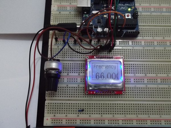
Step 2: First Part : LCD Nokia 5110
This LCD was an Official LCD For Nokia 5110 Phone , It has a dimensions of 84*48 and can be interface on SPI Protocol .
I wrote An artical about it in arabic language on My Blog
http://www.genotronex.com/2013/03/nokia-5110-lcd.html
And the best way to program this series of LCD Is U8g library , It’s support many LCD Controller , You can read More About it in this link
https://code.google.com/p/u8glib/wiki/userreference
this LCD comes with different modules , like adafruit , sparkFun , chines stores , No matter what you are using , Just pay attention to Pinout and it’s connection To arduino Board .
For sparkFun LCD you must read this quick start Guide . and for adafruit LCD you well need CD4050 TTL Converter
I used LCD 5110 which is compatible with 5V Logic input “, you can buy one like this from Ebay store .
Step 3: FM Transmitter Module
The FM Transmitter module is the Heart of this project , it comes form ElecHouse and Works on I2C Interface .
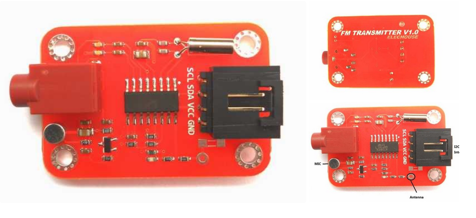
the range of this module without antenna around 40cm , you can connect an external antenna to increase the range of transmitter .
This module based on KT0803K Monolithic Digital Stereo FM Transmitter Radio-Station-on-a-Chip , designed to operate from 76-108 MHZ
the Full Data sheet for KT0803K here
http://www.elechouse.com/elechouse/images/product/FM%20Transmitter%20Module/KT0803K.pdf
the library for this Module will found in the “Arduino Code “step .
Step 4: Potentiometer

There are 2 Potentiometer in this project , One of it “50K ohm” connecting to Analoge Pin A0 to change the frequency of the Transmitter , and the other connecting to pin 7 On the LCD To adjust the Screen Backlight
Step 5: Schematic

the schematic for this project is as following
LCD installation video
FM Transmitter module installation video
potentiometer of the LCD Baclight installation video
Step 6: Arduino Code
The full code , library, and schematic for this project you can find it on attachment
Note that you can change the FM Frequency band depend on your country , in this Line :
fmtx_init(fm_freq, USA); // you can change it for your countery.
/*
USA
EUROPE
JAPAN
AUSTRALIA
CHINA
*/
For My Country ,Jordan , I use USA “Works from 88-107MHz ”
Code ://
/********************************************************************
//This program is distributed in the hope that it will be useful,
//but WITHOUT ANY WARRANTY; without even the implied warranty of
//MERCHANTABILITY or FITNESS FOR A PARTICULAR PURPOSE. See the
// GNU General Public License for more details.
//You should have received a copy of the GNU General Public License
// along with this program. If not, see http://www.gnu.org/licenses/
//Name :Mohannad Rawashdeh .
//Date “13/5/2013 3:00pm
// Description: This Code for A FM transmission station
// for more info http://www.genotronex.com/
// written by :Mohannad Rawashdeh , [email protected]
#include “U8glib.h”
#include <FMTX.h>
// draw Circle
//www.Genotronex.com
//Mohannad Rawashdeh
//U8GLIB_ST7920_128X64 u8g(13, 11, 12, U8G_PIN_NONE);// SPI Com: SCK = en = 18, MOSI = rw = 16, CS = di = 17
U8GLIB_PCD8544 u8g(13, 11, 10, 9, 8); // SPI Com: SCK = 13, MOSI = 11, CS = 10, A0 = 9, Reset = 8
int channel=0;
float fm_freq = 90; // Here set the default FM frequency
int reading=0;
int last_reading=0;
int Current_reading=0;
int mapping_reading=000;
void setup(void){
pinMode(A0,INPUT);
Serial.begin(9600);
fmtx_init(fm_freq, USA); // you can change it for your countery.
/*
USA
EUROPE
JAPAN
AUSTRALIA
CHINA
*/
// Jordan works as USA Frequency range 87.5-110MHz
u8g.setRot180();
u8g.setColorIndex(1); // pixel on !
//……………………………………
u8g.firstPage();
do{
set_screen(1);
}
while(u8g.nextPage() );
delay(1000);
//………………..
u8g.firstPage();
do{
set_screen(0);
}
while(u8g.nextPage() );
delay(1000);
Clear();
//……….
u8g.firstPage();
do{
intro();
}
while(u8g.nextPage() );
delay(2500);
u8g.firstPage();
do{
intro2();
}
while(u8g.nextPage() );
delay(2500);
Clear();
//……………………………………
}
// Reading Any Tunning change here.
void Analog_pin_read(){
channel=mapping_reading;
Current_reading=channel;
fmtx_set_freq(channel);
}
void set_screen(int i){
u8g.setColorIndex(i); // pixel on !
for (int x_axis=0;x_axis<84;x_axis++){
for (int y_axis=0;y_axis<44;y_axis++){
u8g.drawPixel(x_axis,y_axis);
}
}
}
void Clear(void){
u8g .setFont(u8g_font_04b_03);
u8g.setFontRefHeightExtendedText();
u8g.setDefaultForegroundColor();
u8g.setFontPosTop();
}
void intro(void){
u8g.setColorIndex(1);
u8g.drawFrame(0,0,83,47);
u8g .setFont(u8g_font_osr18);
u8g.drawStr( 5, 25, “FM Tx “);
u8g .setFont(u8g_font_tpss);
u8g.drawStr( 5, 40, ” System”);
}
void intro2(void){
u8g.setColorIndex(1);
u8g.drawFrame(0,0,83,47);
u8g .setFont(u8g_font_04b_03);
u8g.drawStr( 2, 7, “Build Your FM station! “);
u8g.drawStr( 2, 15, “Change the Freq”);
u8g.drawStr( 2, 26, “From Poten”);
u8g.drawStr( 2, 38, “www.genotronex.com”);
}
//change frequency value On lcd here
void number(int value){
u8g.setColorIndex(1);
u8g.drawFrame(0,0,83,47);
u8g .setFont(u8g_font_unifont);
u8g.drawStr( 5, 15, “Frequency “);
u8g .setFont(u8g_font_osr18);
u8g.setPrintPos(10,45);
u8g.println(value,DEC);
u8g .setFont(u8g_font_unifont);
u8g.drawStr( 45, 38, “MHz “);
}
void loop(){
reading=analogRead(A0);
mapping_reading=map(reading,0,1023,87,108);
mapping_reading=constrain(mapping_reading,87,108);
if( mapping_reading!= Current_reading){
Clear();
Analog_pin_read();
u8g.firstPage();
do{
number(channel);
}
while(u8g.nextPage() );
delay(100);
}
}
/*******************************
Step 7: Final Video

connect your system to computer for example and bring a Phone with build-in radio and adjust the frequency to listen to your computer music on the radio channel
at the end , the video for the whole system
- What components are required to build this FM transmitter?
You need an Arduino Uno, Nokia 5110 LCD, ElecHouse FM module, jumpers, breadboard, two potentiometers, and a 9V battery. - How do I change the frequency of the transmitter?
Connect a 50K ohm potentiometer to Analog Pin A0 to tune the frequency via the code. - Does the module support different country frequency bands?
Yes, you can change the band in the code by selecting options like USA, EUROPE, JAPAN, AUSTRALIA, or CHINA. - Can I increase the transmission range of the device?
The range is about 40cm without an antenna, but connecting an external antenna increases the range. - What library is recommended for programming the Nokia 5110 LCD?
The U8g library is the best way to program this series of LCDs as it supports many controllers. - How do I adjust the LCD screen backlight?
Use the second potentiometer connected to pin 7 on the LCD to adjust the backlight brightness. - What is the operating frequency range of the KT0803K chip?
The module operates from 76 to 108 MHZ. - How do I connect the system to play music from a computer?
Connect your system to a computer and use a phone with a built-in radio tuned to the transmitter's frequency to listen.