
Summary of Buggy Wheelchair Robot using an Arduino
This article details a DIY project modifying an electric wheelchair, named "Buggy," to be controlled by an Arduino. The author replaced the original batteries and charger with a 24VDC power supply. The core modification involves bypassing the joystick's control signals using DPDT relays and an Arduino Uno to simulate joystick inputs via PWM signals. An old Hitachi LCD from a fire alarm panel is added for status display. The system allows for future automation while retaining the seat for children.
Parts used in the Buggy Wheelchair Robot:
- Electric wheelchair (with intact seat)
- 24VDC Power Supply
- XLR Microphone type plug
- New Batteries (24VDC compatible)
- Two DPDT Relays
- Arduino Uno circuit board
- Ribbon cable from joystick to controller
- Circuit board for soldering connections
- Strain relief bushing
- 22 AWG 6 conductor wire
- Transistors
- Hitachi LCD display (from old fire alarm panel)
This is a Modification of an electric wheelchair.
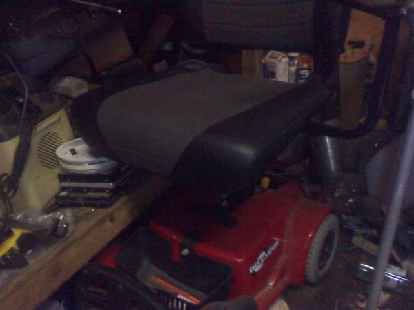
I called it “Buggy” for two reasons. #1 My kids can still ride it around because I left the seat intact. #2 I haven’t programmed anything for a long time.
I plan to create “jobs” for it in the near future.
I welcome any input. Keep in mind this is my first Instruct-able.
I found this chair on-line for a great price. The claim was that it was broken. The OEM battery charger had 2 volts output, the batteries are 24vdc. I found a 24VDC power supply and used the XLR plug that I cut from the charger and it worked fine. I did have to replace the batteries, they were old and tired.
Step 1: Getting Power
This is the connector for the battery charger. It is a standard XLR microphone type plug. This can be connected at the joystick body or into the battery pack at the base.
With the center pin down, top left is green. This is Positive 24VDC. Top right is white. This is Negative 24VDC. The bottom center pin, from what I’ve read, is a programming pin to adjust various operating protocols for the drive systems. The manufacturer of this model doesn’t share programming protocols.
Step 2: Inside the box
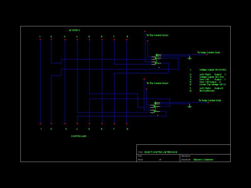
Upon power-up, the controller verifies that the joystick is centered. The voltage supplied at center is about 2.5 VDC. Knowing this I needed to allow the power-up to complete before I took control. So I used two DPDT Relays. Each directional feed from the joystick has two control lines, pins 2,4 and 5,7. I connected the common on the relay to the feed from the control board, the N.O. to the Arduino Uno circuit and the N.C. to the joystick.
Step 3: Who’s in control
I had cut into the ribbon cable from the joystick to the controller. As shown in the schematic a few of the lines carry straight through. I soldered them all to a circuit board. This is the point that I broke out the directional lines to go to the relay bypass. Then as seen in the picture I had to cut the board in two to get it to fit into the joystick housing. I ran the relay control lines and the Arduino control line through a hole I drilled into the Joystick housing. Use a strain relief bushing and BE CAREFUL, when drilling. While in there I also soldered a 22 AWG 6 conductor (22/6) to the labeled test points that control power, on / off, speed control, 5 VDC supply and ground, and a spare conductor. These points can be found running down the left side of the control board. Then I closed and re-mounted the joystick on the wheelchair.
Step 4: Connecting the systems
Once our relays kick on and connect to the Arduino we will need to make sure we produce the 2.5vdc needed to keep the joystick from going in error mode. Remember, if the joystick is not centered (2.5Vcd) it will lockup and stop all operations. If you view the schematic showing pins 9 and 10 PWM, you will see how I connect the output of the Adruino to the input of the joystick. Using the joystick’s 5vdc feed into the transistor and modulating it through the PWM output I can control the variance between the 4.0vdc and the 2.0vdc for forward / backward or left / right requests. This is controlled by activating the relay and then changing the PWM to get the direction that I want.
Step 5: Aux Controls
Activating the unit and controlling the speed. Again using the source 5vdc from the joystick controller I am tripping a transistor to pulse each input. The power and speed buttons are momentary, in this case I will use the software to turn the output pin on the Arduino high then low with a 500ms delay, simulating a button press.
Step 6: What’s it doing.
While working on this project I was given an old fire alarm panel. This panel had a Hitachi LCD display. This display, as I found is one of the most popular types available. So using one of the many examples on-line, I connected it to the Arduino. I use the LCD display to show me what the software is up to, Ie. on-line, power control, forward, backward, etc. I accomplished this using a simple LCD print command at each instruction. I also printed each “direction” to serial output as well.
wheelchair
For more detail: Buggy Wheelchair Robot using an Arduino
-
Why was the wheelchair modified into a robot?
The author modified it because they had not programmed anything in a long time and wanted to create jobs for it. -
How was the power issue resolved when the OEM charger failed?
The author found a 24VDC power supply and used the XLR plug cut from the original charger, which worked fine after replacing old batteries. -
What voltage does the joystick require at the center position?
The voltage supplied at the center of the joystick is about 2.5 VDC. -
How does the system prevent the wheelchair from locking up during power-up?
The author uses two DPDT Relays to allow the power-up to complete before taking control, ensuring the joystick remains centered initially. -
How are forward and backward directions controlled?
The Arduino modulates the joystick input between 4.0vdc and 2.0vdc using PWM output through a transistor to request direction changes. -
How are the power and speed buttons simulated?
The software turns the Arduino output pin high then low with a 500ms delay to simulate momentary button presses. -
Where did the LCD display come from?
The Hitachi LCD display was obtained from an old fire alarm panel given to the author. -
Can the original seat still be used?
Yes, the seat was left intact so the author's kids can still ride it around.
