In this instructable the main focus lies on the software which I’ve created – not so much on the hardware side. You needn’t to use a high- power led for this, you can use every RGB- LED you like.
I’m very impressed by all of these very detailed instructables you can find here, so please indulge me because this is my first instructable and I think I’ve forgotten to write down a lot which could be helpful to rebuild this project. Also the source code is not perfect, so if you have any questions or suggestions please contact me or write down a comment. My only intention to publish all the work is to make it better with the power of the community.
Thank you!
🙂
Step 1: Parts and useful links
What you need to realize it without a high power LED circuit:
- (1) Arduino UNO
- (1) ElectricIMP “SD”-card and a IMPShield or IMP- Breakout board (Sparkfun product page)
- (1) breadboard for prototyping
- (1) RGB- LED
- (1/ optional) Philips Hue starter package
You also need a local webserver. For example a Raspberry Pi with Lighttpd- web server with php- support. You’ll find more information here or with help of google:http://www.raspberrypi-spy.co.uk/2013/06/how-to-setup-a-web-server-on-your-raspberry-pi/
You need the local webserver because Philips Hue isn’t very secure to let it operate in the internet with portforwarding, there is no authentication mechanism.
As mentioned before, the focus lies on the software side, but in the next step you’ll find a short description of the high power led circuit I’ve built…
Step 2: Hardware Setup / LED driver shield (optional)
If you want to use a “normal” RGB- LED, connect it to following Arduino- pins: 11(red), 10(green) and 3(blue). The pins must be pwm- pins! Don’t forget to use series resistors for the RGB LED. Here will you find a good documentation:http://learn.adafruit.com/adafruit-arduino-lesson-3-rgb-leds/overview
Stack the ElectricIMP- shield to the Arduino. Or connect the IMP- breakout to the Arduino:
The Imp’s UART pins are 5 (TX) and 7 (RX) and connected to the Arduino pins RX on 8, TX on 9.
—OPTIONAL—
… for a high power LED you need an own voltage supply circuit:
Parts you’ll need:
- (1) high power LED 3*1W RGB
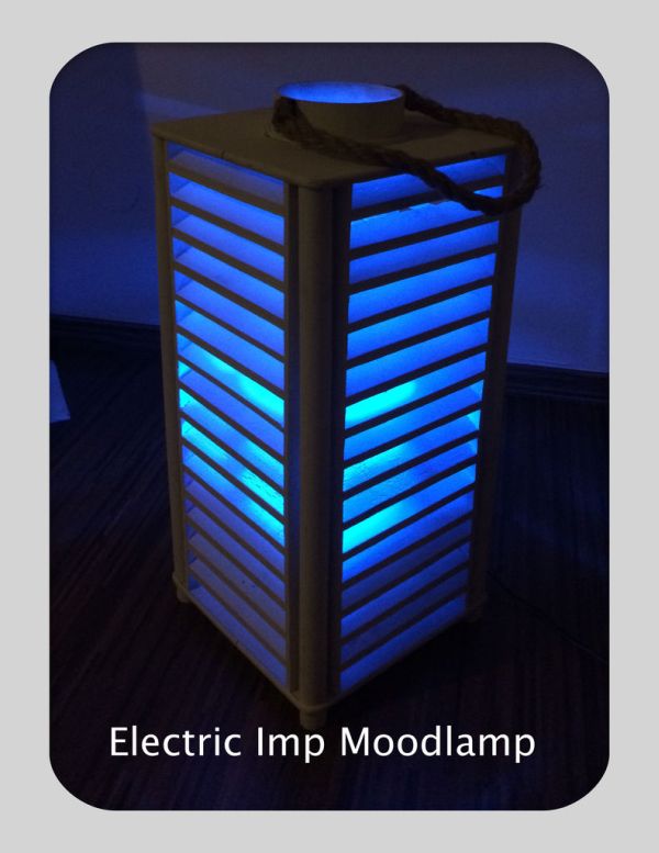
- (1) case for the lamp (for example an “Ikea Lampan” lamp) just be creative, my one was a birthday present
- (3) 1 W(!), 1.4 Ohm resistors
- (3) Mosfets, N-channel (Fairchild FQP50N06L for example)
- (3) 100k Ohm resistors 1/4W
- (3) NPN transistors (Fairchild 2N5088BU for examples)
- (3) Screwterminals (en mass 6 pins)
- (4) Stackable header pins to build an arduino shield (https://www.sparkfun.com/products/9279)
- (1) 12V Powersupply,1500mAh
- (1) Heatsink for the led module
- (1) Stripboard
- (1) self-adhesive thermal pad (M3 thermal pads)
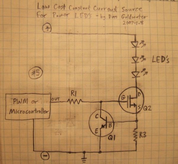
The instructable http://www.instructables.com/id/Circuits-for-using-High-Power-LED-s/?ALLSTEPS was very helpful for me. For every color, I’ve adapted the above shown circuit (rgb), sorry I needed to “steal” the image, technically I couldn’t embedded to this instructable.
„The main current flow is through the LED’s, through Q2, and through R3. When too much current flows through R3, Q1 will start to turn on, which starts turning off Q2. Turning off Q2 reduces the current through the LED’s and R3. So we’ve created a “feedback loop”, which continuously monitors the LED current and keeps it exactly at the set point at all times. transistors are clever, huh!“ Source:http://www.instructables.com/id/Circuits-for-using-High-Power-LED-s/?ALLSTEPS
You need to know the specs and size for the resistor R3. In my case it’s 1.4Ohm (1Watt resistor!!) – let’s calculate:
Have a look at the rgb- module datasheet, there you’ll find the right current value: In my case every color of the LED can have 350mA.
Formular: 0.5A (at 0.5A Q1 is switching) / current = resistor (500mA/350mA=1.43 Ohm).
You’ll find detailed information about the calculation here:
http://www.tbideas.com/blog/build-an-arduino-shield-to-drive-high-power-rgb-led/
My circuit:
The RGB-LED module is connected by a screwterminal with the Arduino- pins 11(red), 10(green) and 3(blue). The pins must be pwm- pins!
The power supply (12V) is directly connected to the Arduino. The LED- Modules 12 line is directly soldered to the power jack- pin of the Arduino.
At this moment, that’s it from my side how to solder your own RGB- shield. In the next days I’ll upload a “Fritzing file” where you can see more details about the circuit. I think you’ll be able to find all necessary informations at the links I’ve posted here.
Step 3: Setup the software
Prerequisites:
You’ll find all the source code here:
https://github.com/andstdout/ElectricImp–Arduino-cloud-based-Mood-Lamp
Your local web server must be accessible through the internet with help of port forwarding and a dyndns- name. Dyn.com published a good howto here:http://dyn.com/support/wizard/
After you’ve downloaded the files from github, you’ll need to customize the files and put them in the right location, let’s begin:
Download and unpack the files from my GIT- repository:https://github.com/andstdout/ElectricImp–Arduino-cloud-based-Mood-Lamp/archive/master.zip
Create a folder called “HSL” at your local webserver:
/var/www/HSL
You’ll need to secure the HSL folder on your web server with .htaccess. There is no need to reinvent the wheel so please have a look at this documentation (for example):
http://www.cyberciti.biz/tips/lighttpd-setup-a-password-protected-directory-directories.html
Put the files from the downloaded and unpacked folder “HTML/HSL” to the “HSL” directory on the web server.
I’ve configured a samba share at the webserver which included the /var/www directory to copy all these files.
Here you’ll find a short samba documentation:https://help.ubuntu.com/community/How to Create a Network Share Via Samba Via CLI (Command-line interface/Linux Terminal) – Uncomplicated, Simple and Brief Way!
Step 4: Setup ElectricIMP agent & device code
If you haven’t yet created your ElectricIMP login, please sign in and configure your ElectricIMP device as described here:
http://www.electricimp.com/product/blinkup/
or here:
http://www.instructables.com/id/Getting-Started-with-Electric-Imp/
Login to the ElectricImp- DevCenter and create a new model, you can name it “Moodlamp” for example.
Copy and paste the code from the downloaded git- archive “ElectricImpCode/Moodlamp_Controller_AGENT.nut” to the agent code area.
Modify the following lines of the agent code (line 3-5):
//CUSTOM Vars:
webserver <- “http://YourWebServerUrlHere.com/“; //Your Webserver URL…
webserverAuth <- “BASE64 KEY” //Your .htaccess authorization key, have a look here: http://www.base64encode.org
weathercity <- “New York”; //Your location to display the actual weather with help of http://openweathermap.org
//——————————————
The .htaccess authorization key is encoded as a base64 key, so encode your .htaccess authorization key with help of the above named online tool. Syntax is username:password
Next, copy and paste the “Moodlamp_Controller_DEVICE.nut”- code to the IMP device code area.
Please note your ElectricIMP- API key, you’ll need it for the next steps:
You’ll find it in the log area, when you build and run the code:
2013-11-12 18:00:07 UTC 1: [Agent] ElectricImp agent started onhttps://agent.electricimp.com/YOURSECRETKEY
For more detail: High Power RGB LED Moodlamp which syncs with Philips Hue