Back in the time when I was building my Arduino based Ludwik Drone I faced a problem of choosing proper motors and propellers. I didn’t know anything about drones at that time so I had to trust motor manufacturer and the datasheet of a motor those are most likely to be a good source of information but what if you want to combine different motors and propellers together? You still need to know the thrust of the motor and propeller, golden rule for drones is to have at least 2 times bigger thrust than weight of your drone (it depends on what type of drone you want to build this rules doesn’t work for racing/acrobat drones and some other). I thought that there must be a device for measuring thrust of a motor, I found some online but those were really expensive so an obvious decision for me wast to design my own! I found some time during my internship at CIT (I was working on airfoil design and testing for a VTOL drone here, that was very cool!) to design a PCB without prototyping and any of the parts, just online datasheets. Surprisingly PCB work just fine! If you want to test your motors keep reading!
Step 1: Parts
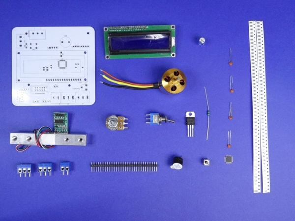
We will need components that are listed below, check out values of them on the schematic:
- Tensometric beam: https://goo.gl/e2aDRA
- LCD: https://goo.gl/WF7dPE
- Motor + ESC + prop: https://goo.gl/WF7dPE
- Current sensor: https://goo.gl/WF7dPE
- Buzzer: https://goo.gl/WF7dPE
- 2 hole screw terminal: https://goo.gl/WF7dPE
- 3 hole screw terminal: https://goo.gl/WF7dPE
- Potentiometer: https://goo.gl/WF7dPE
- Switch
- Breakaway Headers
- potentiometer
- Kanda socket
- Some SMD resistors
- Atmega328 SMD
- Some ceramic capacitors
- Choke
- PCB
Step 2: PCB
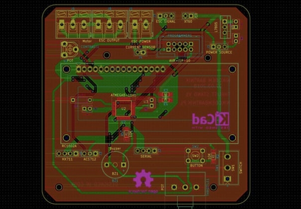
I spend a lot of time on the design of the PCB, I wanted to make it as perfect as I could and it turned out quite nicely! At least it looks more professional than my other PCBs 😀 Above you can find files to make your own PCB. There is also schematic if you want to build it on a breadboard or protoboard (you can do it without any problem). There is a lot of things I add to the PCB because after analyzing it I thought it will be easier to use. For example, I added screw terminal to connect motor and ESC so if you want to test another motor you don’t have to unsolder it. There are also more components than I am actually using (I don’t use voltage regulator because I am using Battery Eliminator Circuit (BEC) build in to Electronic Speed Controller (ESC). There is also a switch and button that I am not using but maybe you would like to change a code or add some functionality.
https://www.pcbway.com/project/shareproject/Brushless_motor_thrust_stand_with_Arduino.html
Step 3: Soldering
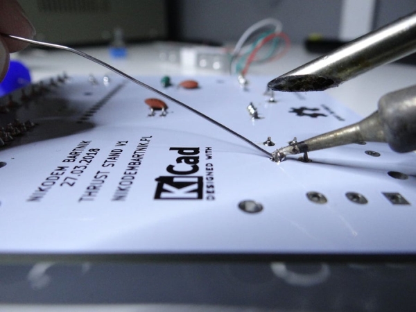
If you are building on a breadboard you can skip this step but for a PCB it’s kind of essential 🙂 As always while soldering start with the smallest SMD components. Atmega328 SMD is not easy to solder so if you have no experience maybe ask for help. Atmega is hidden below LCD display. Tensometric beam module should be also soldered to the PCB as you can see above. Current sensor should be soldered on the bottom of PCB (I know that’s not the best solution but works kind of fine for me).
Step 4: Base
We also have to build a base and 3D print some components. I used 8mm plywood as base and print out those STL files with black PLA. Then I fixed everything with screws.
Step 5: Code

Here is code that you have to upload to the Arduino, it’s really simple and short all it do is reading data from sensors and displaying it on LCD screen, no sophisticated math or any fancy programming things. I am not a fan of comments in the code so if you have any question just ask me 🙂
#include "HX711.h"
#include

#include
LiquidCrystal lcd(4, 3, 5, 6, 7, 8);
#define calibration_factor -400000.0
#define ESC_PIN 9
#define POT_PIN A0
#define BUZZER 2
#define CURRENT_SENSOR A2
#define VOLTAGE_PIN A1HX711 scale(A4, A5);
Servo esc;
void setup() {
  pinMode(BUZZER, OUTPUT);
  lcd.begin(16, 2);
lcd.print("Thrust Stand 1");
delay(1000);
  scale.set_scale(calibration_factor);
  scale.tare();
  esc.attach(ESC_PIN);
  while(analogRead(POT_PIN) > 20){
    lcd.print("TO START SET");
    lcd.setCursor(0,1);
   lcd.print("THROTTLE TO 0");
    delay(200);
    lcd.clear();
  }
}void loop() {    float current=0.0;
long int sum_of_reads = 0;for (int x = 0; x < 100; x++){
  sum_of_reads += analogRead(CURRENT_SENSOR);
  delay(2);
}
delay(50);
lcd.clear();
current = sum_of_reads/100;
current = (2.5 - (current * (5.0 / 1024.0)) )/0.066;
current = abs(current);
current -= 0.07;
current = abs(current);int escValue = map(analogRead(POT_PIN), 0, 1023, 900, 2000);
  esc.write(escValue);
  lcd.print("T:");
  lcd.print(abs(scale.get_units()));
  lcd.print("kg ");
  lcd.print("C:");
  lcd.print(current);
  lcd.print("A");
  lcd.setCursor(0,1);
  lcd.print("E:");
  lcd.print(escValue);
  lcd.print(" P:");
  lcd.print((((analogRead(VOLTAGE_PIN)*5.0)/1024.0)*3.5)*current);
  lcd.print("W");
  if(escValue > 1500){
    if(digitalRead(BUZZER) == HIGH){
      digitalWrite(BUZZER, LOW);
    }else{
      digitalWrite(BUZZER, HIGH);
    }
  }else{
    digitalWrite(BUZZER, LOW);
  }}
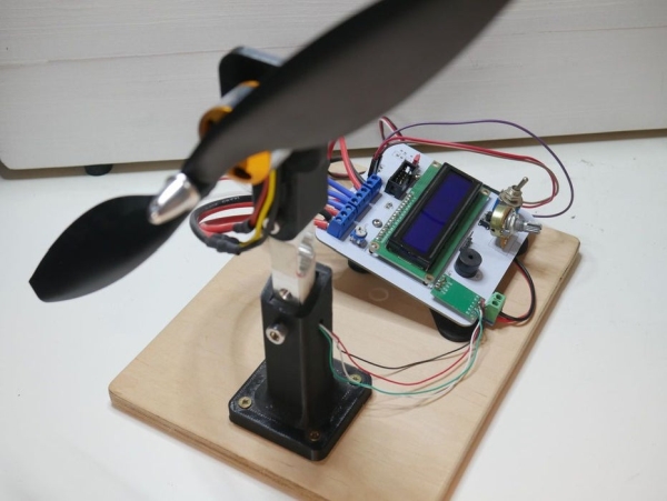
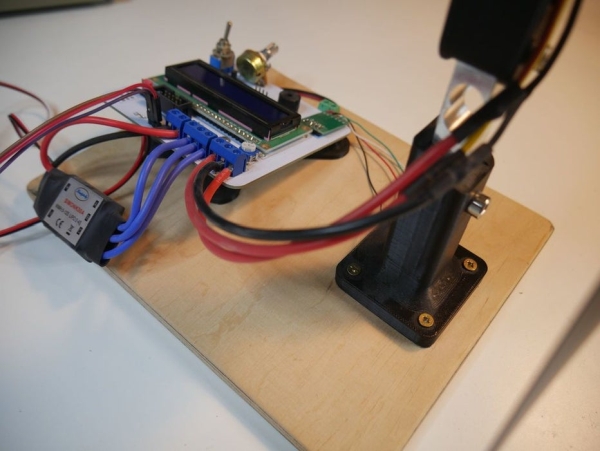
Step 6: Test

Once everything is ready we can test it! Be careful, brushless motor is really powerful and with that big propeller, it’s really dangerous. To power it, you can use anything that works with your motor and ESC (if you use BEC power). I am using my lab bench power supply which is sometimes not powerful enough for this motor. On the LCD screen, you can see thrust, current, throttle value and power consumption of the motor. That’s essential data to design a good quadcopter and find a proper propeller for a motor
Step 7: Conclusion

I hope you enjoyed this instructable! Let me know if you have any questions/ideas in the comments!
YouTube: https://goo.gl/x6Y32E
Facebook: https://goo.gl/ZAQJXJ
Instagram: https://goo.gl/JLFLtf
Twitter: https://goo.gl/JLFLtf
Happy making!
Source: Brushless Motor Thrust Stand