Introduction
Coffee is a beverage consumed around the world for both its sensory and functional properties. Coffee’s taste, aroma, caffeine and antioxidant content are just a few qualities that have made the coffee industry so successful. While the green beans origin, quality, and species all effect the quality of the end product, the roasting of coffee is the most influential factor.
Typically, during roasting, the roast master (a highly trained individual) uses properties of the beans such as temperature, texture, smell, sound, and color to evaluate and adjust the roast accordingly. After roasting, the coffee beans are assessed to ensure bean quality. The Agtron Process Analyzer is an industry standard instrument used to measure thedegree of roastof coffee beans using near-infrared abridged spectrophotometry. The degree of roast is essentially a measurement of the coffee’s quality based on the extent of heat transferred during the roast and categorizes coffee into light, medium and dark roasts.
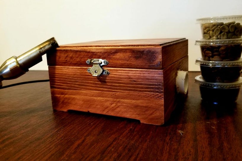
There has recently been a growth of small roasting companies offering custom in-house roasts. These companies are looking for less expensive alternatives to hiring and training a roast master or using the expensive Agtron Process Analyzer. The Degree of Roast Infrared Analyzer for Coffee Roasters, as described in this document, is meant to be an inexpensive means of measuring the degree of roast of coffee beans. The Degree of Roast Infrared Analyzer uses a tryer, a tool found on coffee roasters used to sample the coffee during roasting, to hold a sample of coffee. The tryer is inserted into the analyzer where the AS7263 NIR Spectral sensor is used to measure 6 different infrared bands (610, 680, 730, 760, 810, and 860nm). The reflectance measurements are transmitted via Bluetooth and can then be correlated to the degree of roast. The analyzer must first be calibrated by pressing a button on the inside of the box in which the PVC is used as a white balance as it has a relatively flat reflectance in the spectral range detected by the sensor.
Step 1: Materials
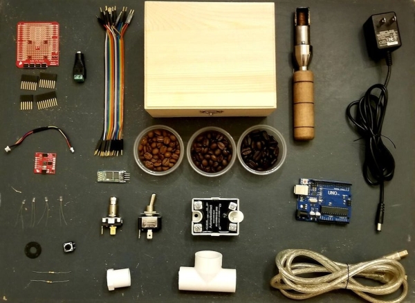
List of Materials
- SparkFun Qwiic Shield (https://www.sparkfun.com/products/14352)
- SparkFun Qwiic Connector (https://www.sparkfun.com/products/14427)
- SparkFun AS7263 NIR Spectral Sensor (https://www.sparkfun.com/products/14351)
- 4 x VCC 6150 Lamps 5V .06A (Incandescent Bulbs) (https://www.mouser.com/)
- 2 x Momentary Push buttons
- 2 x 10kOhm Resistors
- DC Barrel Jack Female (https://www.sparkfun.com/products/10288)
- HC-05 Bluetooth Module (https://www.amazon.com/)
- Power Switch
- Solid State Relay (AD-SSR6M12-DC-200D)(https://www.automationdirect.com/)
- 1/2″ PVC Cap
- 1/2″ x 1/2″ x 3/4″ PVC Tee
- Craft Box (Hobby Lobby)
- Arduino Uno
- Tryer
- 5V 2A power supply (https://www.adafruit.com/product/276)
- USB Cable – Standard A-B (Programming Cable)
Notes on Materials
VCC 6150 Lamps – These are incandescent bulbs chosen because of their high infrared output. The incandescent bulbs are used instead of the LED light provided on the AS7263 module because the onboard LED does not emit the infrared output needed to reflect off of the coffee beans and to be subsequently measured by the sensor. Additionally, it is important to note that in this design the incandescent bulbs are powered from the 5V 2A power source and controlled by the Arduino via a relay. SparkFun does provide two onboard soldering pins on the AS7263 module for the purpose of powering and controlling an auxiliary light source, however these pins are not used because they do not provide enough voltage or amperage to sufficiently power the chosen incandescent bulbs.
SparkFun Qwiic Shield – This shield is used because of its ability to easily connect to the AS7263 sensor via a Qwicc connector. The shield also provides both 3.3V logic level shifting and a large prototyping area.
Solid State Relay – This kind of relay was chosen because of its fast and quiet switching capabilities, however, it is expensive and unnecessary as a standard electrical relay would work as well. If using a standard electrical relay, the code may need to be modified to slow the sampling and calibration process.
PVC size – The PVC size was chosen because of the diameter of the tryer on hand and should be changed if using a different size tryer.
HC-05 Bluetooth Module – An instructables (https://www.instructables.com/id/How-to-Set-AT-Command-Mode-for-HC-05-Bluetooth-Mod/) was used to change the baud rate of the module from 9600 to 115200 to match the baud rate of the AS7263.
Step 2: Wiring Diagram
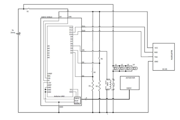
S1 — Power Switch
SSR1 — Solid State Relay
B1 — Sampling Button
B2 — Calibration Button
R1 — 10kOhm Resistor
R2 — 10kOhm Resistor
L1, L2, L3, L4 — Incandescent Bulbs
Step 3: Mounting Incadesent Bulbs to the AS7263
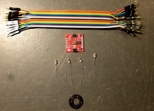
A 3D printed mounting ring (STL provided) was made to hold the lamps around the sensor. The lamps were wired in parallel and hot glue was used to keep the leads of the lamps from touching each other. Liquid rubber insulation can be used instead of hot glue. Next, tiny wires were used to secure the mounting ring to the sensor by tying the wires through the holes provided on the sensor.
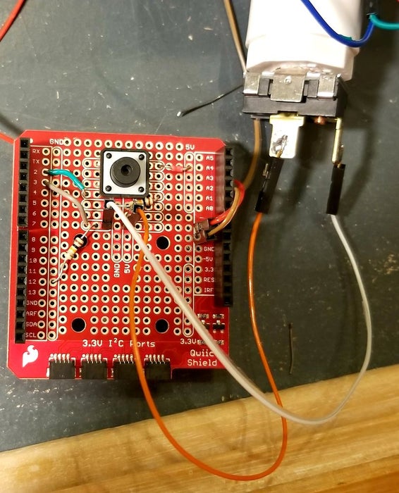
Step 4: Assemble the Tryer Port
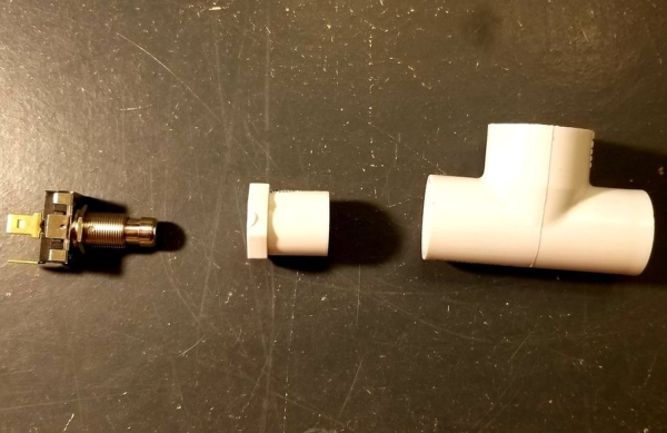
A hole was drilled into the back of the PVC cap to accommodate the momentary push button. The 3/4″ side of the PVC tee was cut off and zip ties were used to secure the sensor to the tryer port. The length of the tee may need to be adjusted to accommodate the size of the tryer. A notch was put into the port side of the PVC tee to align the bean sample in the tryer with the sensor.
Step 5: Wiring the Solid State Relay and Power Switch
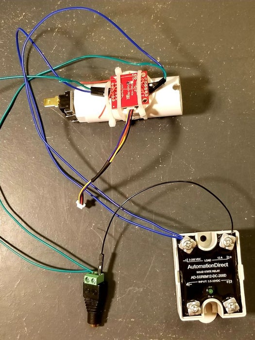
The lights from the were wired in series with solid state relay and the DC barrel jack.
The Vin on the Qwiic shield was connected to the DC barrel jack through a power switch.
The Ground on the Qwiic shield was connected to the ground of the DC barrel jack.
Step 6: Wiring the Calibration Button
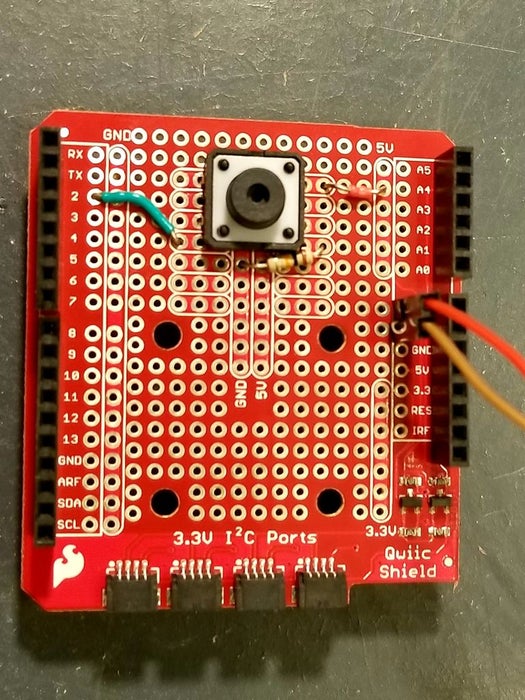
The calibration button was connected to power, Digital 2, and ground using a resistor.
Step 7: Wiring the Sampling Button
The sampling button was connected to power, Digital 3, and ground using a resistor.
Step 8: Wiring the INPUT to the Solid State Relay
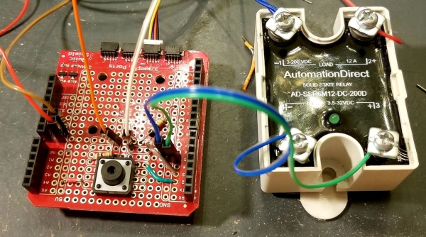
The input side of the solid state relay was wired to Digital 5 and ground.
Source: Degree of Roast Infrared Analyzer for Coffee Roasters