A few weeks ago I made a freeform Arduinoflake. Lot of you loved it. But its magic is not only being freeform but also in the pattern of the LEDs. So I decided to create a PCB version which would be really easy and cheap to make for everyone! It’s the same beauty in a different coat. This tutorial will show you how I designed my Arduinoflake and what it can do!
What is the Arduinoflake?
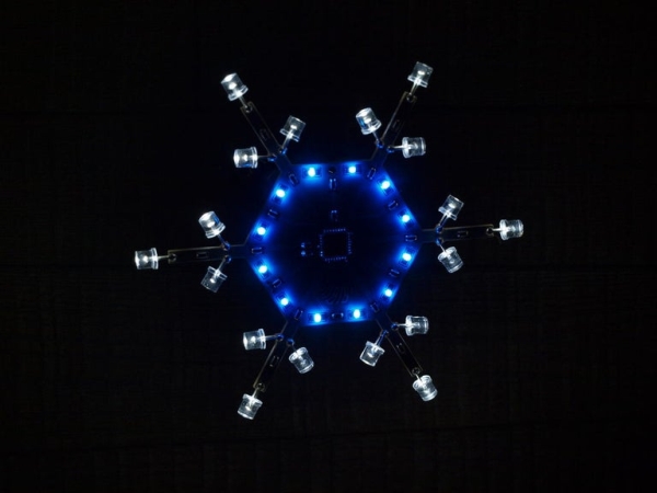
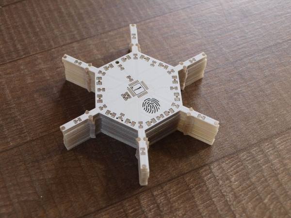
Arduinoflake is a beautiful frozen-looking snowflake. It has 18 wide-angle flat-top LEDs uniquely mounted on sides of PCB and 12 SMD LEDs mounted in the center of PCB. In total there are 30 LEDs grouped into 18 independently controllable segments. They can be used to create whatever crazy animation or pattern you like, and what more you can program it on your own using Arduino IDE. With an integrated touchpad, you can interact with it to switch between animations. A bit boring, isn’t? But what if I told you that you can play a game on it? I hacked mine to play a simple classic snake, see video at the end.
If you would like to have your own Arduinoflake you can consider buying a kit or fully assembled one my tindie store.
Step 1: Electronics Design
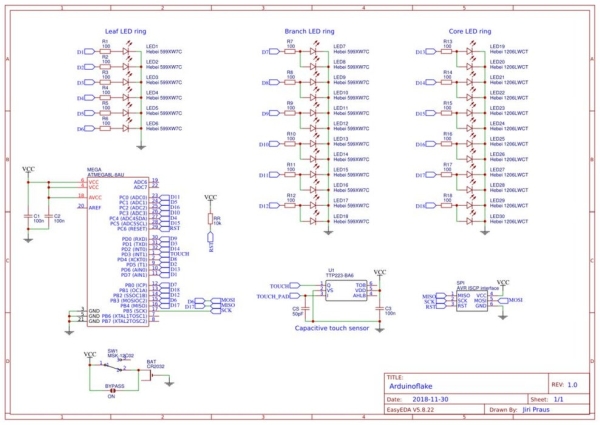
Arduinoflake consists of 30 LEDs grouped into 18 segments, that can be controlled independently. To control these I am using ATmega8 which has up to 22 I/0 pins. Furthermore, I picked a low power version of it (ATmega8L) which can run even on 2.7V which is great for a 3V coin cell battery. Each group of LEDs is connected to one of the ATmega’s I/O pin via a 68R current limiting resistor. Another great feature of Arduinoflake is touch button to interact with it. ATmega does not provide a built-in hardware capacitive touch feature, thus I’ve decided to go with a TTP223 IC. TTP223 is connected to one of the ATmega’s input pin and will drive it high when touch is detected on the touchpad. Another option is to emulate capacitive touch in software but I found out that it takes too much power and computation time.
Step 2: Creating an Outline of PCB
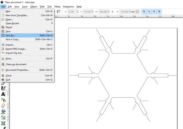
The board is going to be quite a complex one. Hexagonal base with 6 beams in each corner, each with 3 spots for LEDs to be mounted on. If you will be using EasyEDA online tool for designing the PCB like me you will need graphics in DXF format (AutoCAD Drawing Exchange Format) to import it into EasyEDA, because EasyEDA is not capable of drawing such a complex shape. I’ve used Inkscape. It’s the only vector tool I am used to that allows exporting into DXF files.
Step 3: Creating PCB Layout
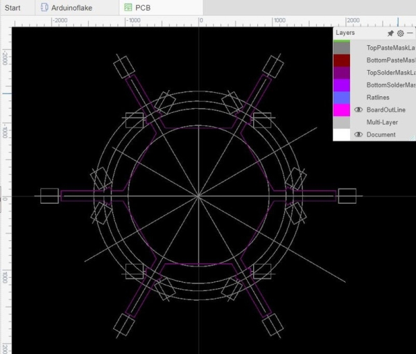
If you have your outline graphics, import it into EasyEDA into BoardOutLine layer. I’ve also drawn an auxiliary graphics to help me with aligning all the parts and routes on the board under the 30 and 60-degree angles and imported it into Document layer. I also made myself a special component in EasyEDA for THT LEDs mounted on the side of the board.
Step 4: Manufacturing the PCB
Todays its totally unreasonable to create a PCB in-house since it is incredibly easy, fast and cheap to have professionals to manufacture it for you. And you will end up with the perfect looking board with no trouble. I’ve used a PCBWay manufacturer this time. Apart from the great result, they also had a free PCB for Xmas prototyping campaign so I got them very cheaply. Placing the order is quite simple, you only need to export Gerber files from EasyEDA and upload them to the wizard on the site, then it’s like shopping in an online store. I was most worried about the thin beams, but they came out great!
Step 5: Assembling It
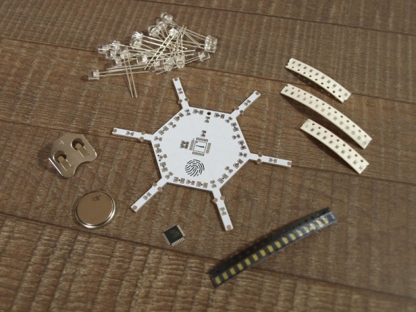
Parts list:
- ATmega8L TQF32
- TTP223 BA6
- 68R resistor 0805 (18x)
- 10K resistor 0805
- 100nF capacitor 0806 (3x)
- 50pF capacitor 0806
- bright white LED 1206 (12x)
- bright white flat-top LED THT (18x)
- battery holder
- SMD on/off switch
- temporary pin header for programming
As you can notice the most challenging part on the Arduinoflake is ATmega8L with its TQF32 package and TTP223, if you can handle those two, the others are piece of cake. First I assembled the resistors, capacitors and SMD LEDs. Second, the microcontroller at the center using a lot of flux and a small amount of solder. Third, the TTP223 on the bottom. Fourth, the uniquely mounted THT LEDs on the sides of PCB. And last but not least, the battery holder, on/off switch and temporary pin header for programming. All with the use of flux and a small amount of solder. After soldering is done, don’t forget to clean the PCB with Acetone to remove all remaining flux.
Step 6: Uploading and Running the Code
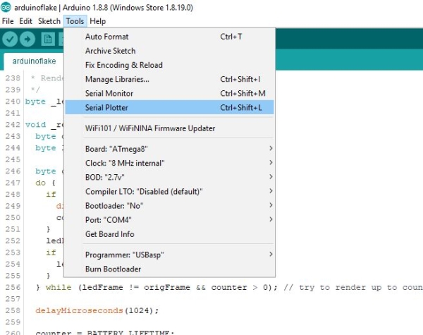
AVR chips are programmed via ISCP programming interface with a help of an external programmer – for example USBasp. If you don’t own an USBasp programmer you can use any Arduino development board and flash it to become “Arduino as ISP” programmer. There are tons of articles on how to do that.
ATmega8 is not supported by Arduino IDE by default, you need to add a board configuration, I am using terrific work of MCUdude – MiniCore library. All instructions on how to install it into your IDE are there. My Arduinoflake is running internal oscillator at 8MHz (no need for an external crystal) and optimized program that saves the power of CR2032 coin battery to run fully lit Arduinoflake for up to 12h. Check out my GitHub repository.
Step 7: Do You Want to Play a Game?
Arduinoflake is not only a decoration but you can also write games for it since it has a touch button, check out my flake snake!
If you would like to have your own Arduinoflake you can consider buying a kit or fully assembled one my tindie store.
Source: Arduinoflake – PCB Version