Summary of Simulated Sports Scoreboard
This article details the construction of a remote-controlled, Arduino-driven 4-digit LED scoreboard for a high school theater production. The author documents the design process, material selection, and assembly challenges, specifically focusing on PCB fabrication errors and display flickering issues caused by multiplexing. The project utilizes custom driver boards, MOSFETs, and acrylic panels to create a simulated championship game scoreboard within strict production deadlines.
Parts used in the Simulated Sports Scoreboard:
- Remote Control module (single channel, relay output)
- Custom Display Driver boards (qty 4)
- 12VDC 5A 60W DC Power Supply
- Arduino Mega 2560 kit (w/ USB cable and power adapter)
- 22 Gauge hookup wire (8 colors)
- TO-220 Heatsink kit (10 pcs)
- 2N7000 MOSFET (qty 32)
- NDP6020P P-Channel MOSFET 20V 24A (qty 4)
- TO-220 Heat Sinks (qty 4)
- 1/8" 10K Resistors (qty 15)
- 8-pin Headers (optional, qty 8)
- 44"x32" acrylic sheet
- ¼" Luan plywood (various sizes)
- 1"x2" Pine Boards (qty 4)
- Misc. hardware
- Solder and solder wick
- Painter's Tape (1" & 1-1/2" widths)
- Vinyl Letters (2-3" high)
- Hook and Loop fasteners (tape)
- Extension cord (25" or longer)
I am the theatrical technical director for a local high school. Their winter production was “Disney’s High School Musical”. During meetings with the director, he said it would be cool if he could have a scoreboard. I excitedly replied that I could make one that worked by remote control. Warning: be careful what you promise.
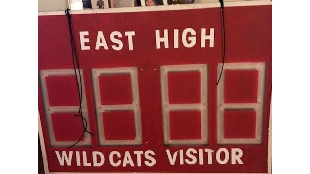
This Instructable describes how I constructed the scoreboard. It wasn’t really an operating scoreboard, but one that simulated the requirements of the championship game within the play. Simply, I constructed an Arduino controlled, 4-digit display constructed from LED strips. The remote control only used one channel, to cycle through a set of pre-programmed scores.
There was a strict production deadline. As such as I ran into problems, I made compromises toward meeting the dates. So, this Instructable is more than my typical construction article. It documents mistakes as well as successes. At times, it diverges into the problems I encountered, what caused them and how to avoid them happening to you.
In particular, most of my issues revolved around the PCB board construction. I hope my experience will prove of value to help you in making your own custom PCB boards.
Also, my sketch for the Arduino produced a noticeable flicker, which could have been avoided by better programming practice. In this application, this wasn’t a critical flaw. However, I provide thoughts as to how I would have avoided this problem.
The display is created by displaying each digit for a short period of time, so that the eye sees all four being shown. This is known as multiplexing.
Note: If you are unfamiliar with 7-segment displays, they are in the shape of a block ‘8’. Each segment is lettered a-g. ‘a’ is the top segment and then continuing clockwise the segments are labelled b-f successively. ‘g’ is the cross segment. By illuminating different segments, the digits 0 through 9 are created. For example, a ‘1’ is displayed by illuminating segments b and c.
Step 1: Materials
- Remote Control module, single channel, relay output
- Custom Display Driver boards (qty 4)
- 12VDC 5A 60W DC Power Supply
- Arduino Mega 2560 kit (w/ USB cable and power adapter)
- 22 Gauge hookup wire, 8 colors
- TO-220 Heatsink kit (10 pcs)
- 2N7000 MOSFET (qty 32)
- NDP6020P P-Channel MOSFET 20V 24A (qty 4)
- TO-220 Heat Sinks (qty 4)
- 1/8” 10K Resistors (qty 15)
- 8-pin Headers (optional, qty 8)
- 44”x32” acrylic sheet
- ¼” Luan plywood (44”x32”, 17”x44” & 12”x44”)
- 1”x2” Pine Boards (qty 4)
- Misc. hardware
- Solder
- Solder wick (optional)
- Painter’s Tape (1” & 1-1/2” widths
- Vinyl Letters, 2-3” high
- Hook and Loop fasteners (tape)
- Extension cord (25” or longer)
Step 2: Electronics Block Diagram
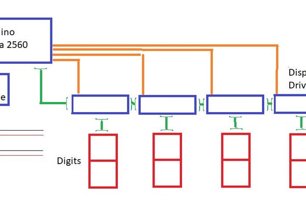
The entire project is constructed of eight modules. They are
as follows
- · 9VDC power adapter – Arduino (commercial product)
- · 12VDC 5A power adapter for the remote-control receiver and the LED strips (commercial product)
- · Remote control receiver & remote (commercial product)
- · Arduino Mega 2560 (commercial product)
- · Digit Drivers (custom PCB)
- · 7-Segment Digits
And the non-electronic components are:
- · Scoreboard Front
- · Scoreboard Rear
The Remote control is powered with 12VDC and its internal relay is used to switch ground to an Arduino I/O pin. The pin is configured as INPUT_PULLUP, which keeps its value high until the remote control switches it to ground. This is important. If your microprocessor can’t do this, an external resistor to Vcc will be required.
The Arduino is powered by an Arduino power adapter (wall wart) at 9VDC. Its ground is connected to the 12VDC ground for driving the digits.
Seven pins of the Arduino are set to display the proper segments for each digit. Four additional pins are used to multiplex the four digits. This is done to avoid using 28 pins just for the display. It also simplifies the wiring and display driver design.
The second picture shows how the component modules are attached with self-adhesive hook & loop fasteners to the back board.
Step 3: Design of the Scoreboard
I wanted something about 3’ by 4’ for the display. My final size selection was based on a standard size acrylic sheet available at Lowe’s. The LED strips I purchased had an LED about every inch. If one segment was 6” (resulting in a 8” by 16” digit), I could place four digits with an extra space between each pair.
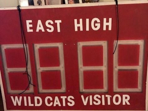
This left me space above and below the digits for lettering on the scoreboard. I did not make this space equal, because it looked better with more space on top.The front layout of the scoreboard is shown in the picture below.
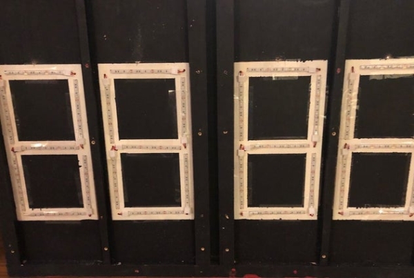
A backing piece of ¼” luan plywood was also cut. 1”x2” pine was used to frame the backboard, as well as separate the digits, so that light from one digit did not splash over to the next. You can see the backing board with the LED strips attached in the first picture
See the layout diagram for the backboard construction in the next step.
Step 4: Making the Backing Board
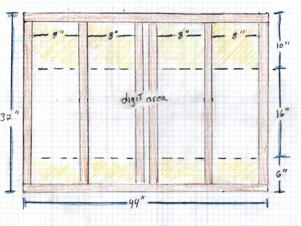
Cut a piece of ¼” luan plywood to the same size as the acrylic sheet, in my case that was 44” x 32”.
Paint the digit area white. The digit area is 10” from the top and 6” from the bottom, for an area of 16” x 44”. Paint an area slightly larger.
Once the paint is dry, use 1”x3” pine to frame the board. I used glue and screws, as the frame must be strong enough to hang the scoreboard from a scenery bar. Also, there are four interior stiles which separate the digits and keep light from bleeding into an adjacent digit. See the picture for the layout.
Now that the frame and stiles are attached, use 1-1/2” wide painting tape to mask the actual digits. The tape should form a block ‘8’ digit/character.
Before continuing, drill seven 1/4” holes in the corners of the digits. These are used to power segments a-f. The cross segment needs two holes. The second hole is for segment g.
Once the digits are all masked, paint the entire backing board assembly black. But, do not paint the rear of the board. It should remain raw wood in order that hook and look fasteners can adhere in order to attach the electronics.
Source: Simulated Sports Scoreboard
- How does the remote control operate the scoreboard?
The remote uses a single channel with a relay output that switches ground to an Arduino I/O pin configured as INPUT_PULLUP to cycle through pre-programmed scores. - What technique is used to display four digits simultaneously?
The display uses multiplexing, where each digit is shown for a short period so the eye perceives all four being lit at once. - Why were interior stiles added to the backing board?
Interior stiles made from pine separate the digits to prevent light from one digit from splashing over into an adjacent digit. - What causes noticeable flicker in the Arduino sketch?
Flicker occurs due to programming practices; while not critical here, better coding could have avoided this issue. - How are the electronic modules attached to the back board?
The component modules are attached using self-adhesive hook and loop fasteners. - What determines the physical size of the scoreboard?
The size was selected based on a standard 44x32 inch acrylic sheet available at Lowe's and the spacing required for the LED strips. - Why must the rear of the backing board remain raw wood?
The rear remains raw wood to allow hook and loop fasteners to adhere properly for attaching the electronics. - How many pins are required to drive the segments and multiplex the digits?
Seven pins display the proper segments for each digit, and four additional pins are used to multiplex the four digits.