Summary of Arduino Wireless SD Shield Tutorial
The Arduino Wireless SD shield integrates Xbee transceivers for wireless mesh networking and a micro SD socket for data storage, significantly expanding standard Arduino capabilities. The article outlines a simple setup process involving plugging in modules, configuring switches between USB and Micro SD modes, and programming the receiver to control external components like LEDs based on wireless signals.
Parts used in the Arduino Wireless SD Shield Project:
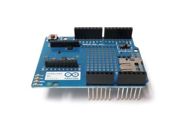
- Arduino Wireless SD shield
- Xbee modules
- Micro SD card
- Arduino board
- 9V battery connector
- LED
- 220 ohm resistor
- Red wire
- Black wire
As the name implies, the Arduino Wireless SD shield serves two functions. Foremost, this shield allows you to easily interface with Xbee transceiver modules to create mesh networks, and other wireless devices. Secondly, the micro SD socket allows you to store and access a large amount of data. Whether using these functions by on their own or together, this chip greatly enhances the capabilities of a standard Arduino. The best part about this shield is how easy it is to use. In no time flat, you can have its various components up and running.
Step 1: Plug in the Xbee
Plug in your Xbee modules in order to use the shield as a wireless transceiver.
Make sure the module’s pointy end is lined up with the edge of the board.
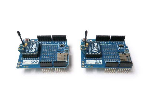
If you are using the shield for wireless data transfer, you will need two or more of them.
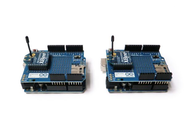
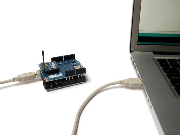
Step 2: Plug it in
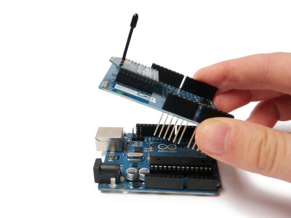
Plug your shields into your Arduinos.
Step 3: Features
The wireless SD shield supports Xbee modules. These modules allow for easy wireless serial communication. A standard module has the range of 100 – 300 feet.
It also boasts a micro SD socket. This can easily be interfaced with the Arduino SD library. Unfortunately, this library does not come bundled with the Arduino development environment, so you will have to set it up yourself.
The shield also boasts a perfboard grid for prototyping your own circuit, and a micro switch for toggling between the USB port and micro SD port.
For more technical information visit its official Arduino page.
Step 4: Program the receiver
Plug one of the Arduinos into the computer. Make certain the micro switch is toggled to the “USB” option.
Upload the following code:
Step 5: Setup the receiver
Unplug the Arduino from the computer. Toggle the micro switch from “USB” to “MICRO”.
Plug the red wire from a 9V battery connector into the Vin pin. Plug the black wire into the GND pin.

Connect the positive leg of an LED to pin D2 and the other leg in series with a 220 ohm resistor to ground.
Plug in your battery.
It is now a standalone receiver.
For more detail: Arduino Wireless SD Shield Tutorial
- What are the two main functions of the Arduino Wireless SD shield?
The shield allows you to interface with Xbee transceiver modules for wireless networks and provides a micro SD socket for storing and accessing large amounts of data. - How do I plug in the Xbee module correctly?
You must ensure the module's pointy end is lined up with the edge of the board. - What is the range of a standard Xbee module?
A standard module has a range of 100 to 300 feet. - Does the Arduino SD library come bundled with the development environment?
No, the library does not come bundled with the Arduino development environment, so you must set it up yourself. - How do I toggle between the USB port and micro SD port?
You use the micro switch located on the shield to toggle between the USB port and the micro SD port. - Which pins should be used to connect a 9V battery connector?
Plug the red wire into the Vin pin and the black wire into the GND pin. - How is the LED connected to the circuit?
Connect the positive leg of an LED to pin D2 and the other leg in series with a 220 ohm resistor to ground. - Can this shield be used for creating mesh networks?
Yes, the shield allows you to easily interface with Xbee transceiver modules to create mesh networks.