
Summary of Arduino Tri-colour LED Flasher Circuit
This beginner-friendly project demonstrates an Arduino Uno controlling a tri-colour LED to cycle through red, green, and orange. The circuit uses a simple three-pin common cathode LED driven by two digital output pins. The provided sketch switches the LEDs every second: activating one for primary colors or both simultaneously to create orange, offering a practical introduction to basic electronics and Arduino programming.
Parts used in the Arduino Tri-colour LED Flasher:
- Arduino Uno
- Tri-colour LED (three pin common cathode)
- Red LED component within the package
- Green LED component within the package
This simple tri-colour LED flasher circuit is great for beginners. The three pin tri-colour LED is controller by an Arduino Uno and changed between three colours. This video shows the Arduino running a sketch that controls the tri-colour LED.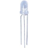
Circuit Diagram for the Arduino Tri-colour LED Controller
The circuit is very simple, using only three components. The tri-colour LED is a three pin common cathode type containing a red and green LED. The tri-colour LED is the same LED used in the tri-colour LED transistor flasher circuit – refer to this project for more details on the LED.
Arduino Sketch
The sketch changes the colour of the LED every second. Colours are changed by switching on the red LED in the tri-colour LED package, then the green LED, orange is obtained by switching on both the red and green LEDs at the same time.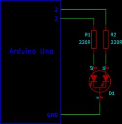 /*————————————————————– Program: tri_colour_LED Description: Changes the colours of a tri-color LED. Hardware: Arduino Uno and tri-colour LED. Software: Developed using Arduino 1.0.3 software Should be compatible with Arduino 1.0 + Date: 8 May 2013 Author: W.A. Smith, http://startingelectronics.org ————————————————————–*/ void setup() { pinMode(2, OUTPUT); pinMode(3, OUTPUT); }
For more detail: Arduino Tri-colour LED Flasher Circuit
- What is the main purpose of this circuit?
The circuit is designed for beginners to control a tri-colour LED between three colours using an Arduino Uno. - How does the sketch change the colour of the LED?
The sketch changes the colour every second by switching on the red LED, then the green LED, or both at the same time. - What type of tri-colour LED is used in this project?
A three pin common cathode type containing a red and green LED is used. - How is the orange colour obtained?
Orange is obtained by switching on both the red and green LEDs at the same time. - Which Arduino software version was used to develop this sketch?
The software was developed using Arduino 1.0.3 but should be compatible with Arduino 1.0 and later versions. - Can this project be built with fewer than three components?
No, the text states the circuit uses only three components including the LED itself. - What pins are configured as outputs in the setup function?
Pins 2 and 3 are configured as OUTPUT in the setup function. - Is there a reference to another similar circuit mentioned?
Yes, the article refers to a tri-colour LED transistor flasher circuit for more details on the LED used.
