Summary of Arduino Thermometer
Concise summary (under 100 words): This Instructable shows how to build a simple desktop thermometer using an Arduino Uno, an LM35 temperature sensor, and a 16x2 LCD. The author describes required parts, wiring between the LCD, LM35, and Arduino, testing the LCD, checking connections with a schematic, adding code to read the LM35 on analog pin A0, and creating a Tupperware case with a cutout for the LCD.
Parts used in the Arduino Thermometer:
- LM35 temperature sensor
- Plastic Tupperware (case)
- Breadboard
- 9V battery
- Arduino 9V clip
- 16x2 LCD
- Arduino Uno
- Jumper wires
Its hot here in Los Angeles! Besides the massive drought California is in, Its not as cool around here lately. I wanted to build something to see just how hot it really was, and here it is!
Read this instructable and Ill teach how you can turn just a few components you have into an accurate mini desktop thermometer!
I hope you enjoy the project and vote for it for the contests!
Lets Build It!
Step 1: You Will Need…
If you would like to make this project, you will need:
- LM35 sensor (Already had)
- Plastic Tupperware (Free)
- Breadboard (Already had)
- 9v Battery and Arduino 9v clip (Already had)
- LCD 16×2 (Already had)
- Arduino Uno (Already Had)
- Wires! (Already Had)
As you can see, you dont need much. In fact I had these pieces lying around my house so this was FREE!
Step 2: Test the LCD
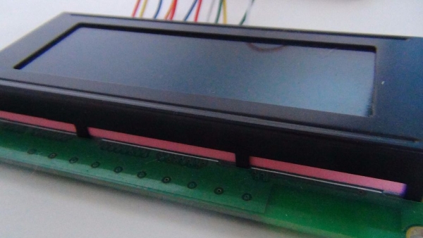
I wanted to test and see if my LCD still worked. It still worked! Heres how I wired it:
LCD Arduino
1…… GDN
2…… 5V
3…… GDN
4…… PIN 8
5…… GDN
6…… PIN 9
7…… –
8……. –
9…… –
10…… –
11…… PIN 4
12……PIN 5
13……PIN 6
14…… PIN 7
15…… 5V
16…… GDN
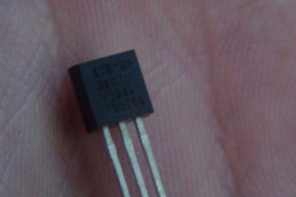
Step 3: Add in the LM35!
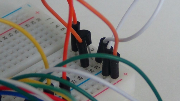
Take the LM35 and add it in! Heres a helpful guide:
(Ignore the periods)
[ LM35 (Front) ]
[…………………. ]
[_]
I…………I………..I
I…………I………..I
I…………I………. I
(5v)….(A0)…..(GDN)
Step 4: Check Your Wiring
We don’t want any mistakes!
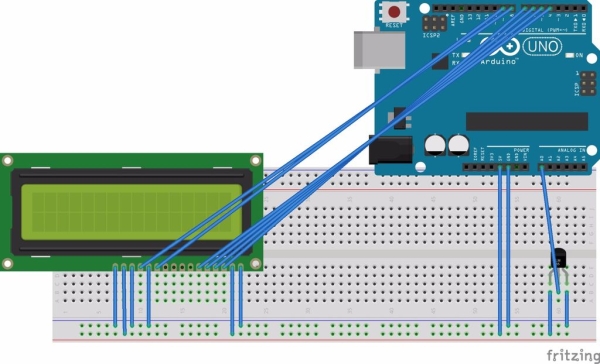
Heres a schematic I used for this project
Step 5: Code!
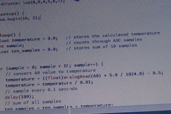
Now its time to code!
Here the code! (Please If you see anything wrong tell me)
Step 6: Measure LCD
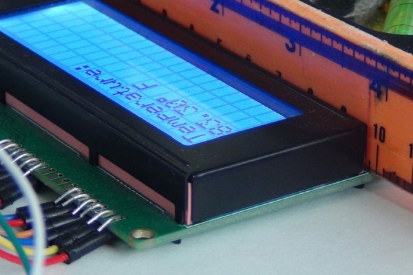
Now its time to make the case
Measure the LCD protruding sceen and cut a hole just big enough to squeeze over the LCD.
Read more: Arduino Thermometer
- What components do I need to build the thermometer?
The article lists an LM35 sensor, plastic Tupperware, breadboard, 9V battery and Arduino 9V clip, a 16x2 LCD, an Arduino Uno, and wires. - How is the LM35 connected to the Arduino?
The LM35 is wired with its pins as 5V, A0, and GND from left to right when viewed from the front as shown in the guide. - How do I wire the 16x2 LCD to the Arduino?
The article provides a pin mapping where LCD pins 1 and 3 go to GND, pin 2 and 15 to 5V, pins 4 and 5 to Arduino 8 and 9, pins 11–14 to Arduino pins 4–7 respectively, and remaining pins as ground or unused per the listed mapping. - Do I need a schematic before powering the project?
Yes; the article advises checking wiring and shows a schematic used for the project to avoid mistakes. - Is testing the LCD recommended before assembly?
Yes; the author tested the LCD first to ensure it still worked before continuing. - Where should the LM35 analog output be connected?
The LM35 analog output is connected to Arduino analog pin A0 as shown in the guide. - Does the project include code for reading temperature?
Yes; the article states there is code provided to read the LM35 and display results, and the author invites feedback if anything is wrong. - How is the final enclosure made?
The author uses a plastic Tupperware case and cuts a hole sized to fit the LCD screen so it squeezes into the case.