Summary of Arduino LED Matrix
This tutorial shows how to build an Arduino-controlled LED matrix that receives display instructions from a companion computer. It includes Arduino code and Java code for text (with a 7x5 font), materials, board drilling, spray-painting, wiring, and caveats about row limits and unavailable audio-visualization code.
Parts used in the Arduino LED Matrix:
- Arduino with enough digital pins (example: Arduino Mega 2560)
- Female-to-male breadboard jumper wires
- LEDs (enough for matrix size, e.g., 35 for 7x5)
- Resistors (one per row as used in the project)
- Wooden board for mounting LEDs
- Companion computer to connect to the Arduino
- Spray paint (for board finish)
- Drill and selection of drill bits (including a 5mm bit)
- Pliers
- Wire clippers or cutters
- Soldering iron and solder
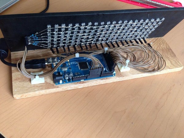
In this short tutorial you will learn how to make an Arduino-powered LED matrix. Unlike several other designs, this one uses a “companion” computer to notify the Arduino which LEDs should be powered.
I have provided the code for the Arduino, as well as some Java code for displaying text on the LED matrix (this includes a custom-made 7×5 character font).
Things to keep in mind:
- With the software provided, a maximum of 7 rows is possible if you want to display text. It would technically be possible to increase this limit to 15, but I’ll leave that to someone else.
- If you want to just display sound values (i. e you want to light up the LEDs consecutively from the bottom), it would be technically be possible to use up to 127 rows.
- I cannot release the code for the audio visualization(sorry!) for various reasons
Step 1: The Materials
For this project, you will need the following materials:
- An Arduino that has as many digital pins as you want rows and columns combined. (eg, If you want to have a 7×5 LED matrix, you need at least 12 digital pins on your arduino). I used an Arduino Mega 2560 as the Mega has 54 digital I/O pins and was the only which allowed me to make a 20 by 7 grid (I needed 27 pins).
- In order to connect your Arduino to the LED matrix, it would be helpful to have female to male breadboard wires
- Enough LED’s for your matrix. (With a 7×5 matrix, you need 35 LEDs). For this project, I used the blue LEDs which can be found here
- The link above also has the resistors you need. You will need as many resistors as you have rows in your LED matrix
- A wooden board for mounting the LEDs. You’ll need some reasonably thin wood for this project. How thick and how big the wood should be depends on how much you want your LEDs to protrude out the front and how far apart you want the LEDs to be spaced. I would recommend a 1 cm spacing between your LEDs(mine were 5mm in diameter). Remember to leave some space on all sides(especially to the left and right of the matrix).
- A companion computer to connect the Arduino to.
- Spray paint for the added effect.
You will also need various tools: drill (+ a selection of drill bits), pliers, clippers(or wire cutters), and a soldering iron(with solder)
Step 2: Cutting/Drilling the Board
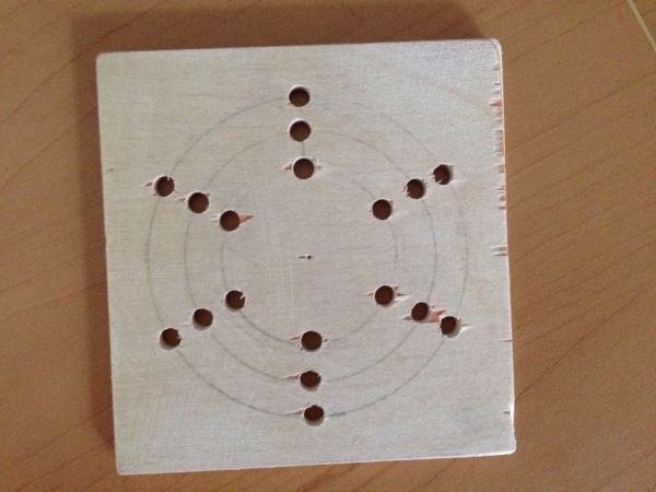
(The picture above is of a prototype board, not the final product. Use it as inspiration to come up with other cool LED patterns)
The first thing you need to construct is the board on which the LEDs will be mounted. Here you have several options on how to structure the LED board. You could design you LED board in the classical, grid LED matrix or you could take a more interesting approach by making a circular LED pattern.
In this step you will also have to take into account the spacing of your LEDs. I would recommend having the centers of the LEDs be 1 cm apart from each so that the LEDs(which are 5mm in diameter) will be tightly packed(but not so tightly it is impossible to work with).
The size drill bit you should use depends on the size of the LEDs. I bought a special 5mm drill bit so the LEDs would fit exactly. Take into consideration that if you are going to spray paint the board, this will make the holes slightly smaller.
Step 3: Spray Painting the Board
If you want to make your board a certain color, then now is the time to do that. Before inserting your LEDs, you should consider spray painting your board (as this will not be an option once the LEDs are in place–you don’t want to spray paint the LEDs).
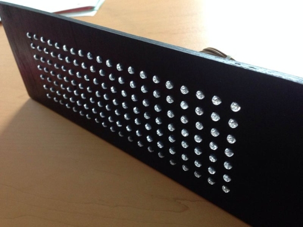
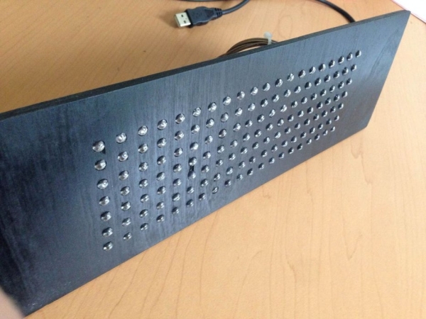
I chose black as the preferred color for my board as I happened to have a black spray paint on hand and thought it would go well with my blue LEDs.
Read more: Arduino LED Matrix
- What does this tutorial teach?
How to make an Arduino-powered LED matrix that uses a companion computer to tell the Arduino which LEDs to light, plus provided Arduino and Java code for text display. - What Arduino was used and why?
An Arduino Mega 2560 was used because it has many digital I/O pins and allowed a 20 by 7 grid; a board must have enough pins for rows plus columns. - How many rows can display text with the provided software?
The software supports a maximum of 7 rows for text display. - Can the matrix support more rows for non-text displays?
Yes; for simple sequential displays such as sound values, up to 127 rows could technically be used. - Are the audio visualization code files available?
No, the author did not release the audio visualization code. - What spacing between LEDs is recommended?
The author recommends about 1 cm center-to-center spacing for 5 mm diameter LEDs. - What drill bit size should I use for 5 mm LEDs?
Use a 5 mm drill bit so the LEDs fit exactly, accounting for possible reduction from spray paint. - When should I spray paint the mounting board?
Spray paint the board before inserting LEDs, because painting after insertion is not practical and will affect hole sizes. - How many resistors are needed?
You need as many resistors as there are rows in the LED matrix as used in this project. - What tools are required?
Required tools include a drill with bits, pliers, wire clippers, and a soldering iron with solder.