Summary of Arduino Sketch Adafruit PWM
This article details an Arduino sketch demonstrating how to control 16 PWM channels using the Adafruit PCA9685 driver via I2C. The code drives all channels in a wave pattern, configuring the frequency and handling communication protocols. It includes main logic, library functions for initialization and data transmission, and header definitions for register addresses.
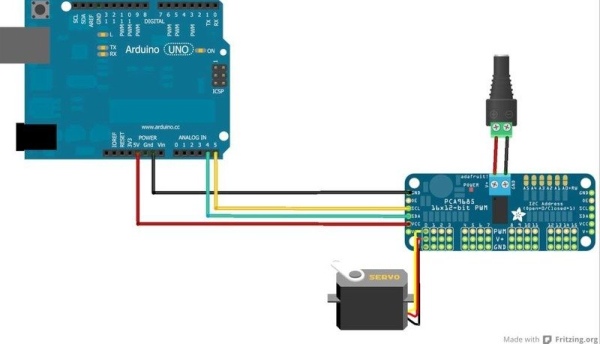
Parts used in the Adafruit PWM I2C Module Project:
- Arduino UNO
- Adafruit 16-channel PWM & Servo driver (PCA9685)
- SCL pin (Analog 5 on Arduino UNO)
- SDA pin (Analog 4 on Arduino UNO)
- Adafruit_PWMServoDriver.h library
- Wire.h library
This sketch is used by Exercise: Adafruit PWM I2C Module.
Full Source Code
The main code is in Adafruit_PWM.ino.
/***************************************************
  This is an example for our Adafruit 16-channel PWM & Servo driver
  PWM test - this will drive 16 PWMs in a 'wave'

  Pick one up today in the adafruit shop!
  ------> http://www.adafruit.com/products/815

  These displays use I2C to communicate, 2 pins are required to
  interface. For Arduino UNOs, thats SCL -> Analog 5, SDA -> Analog 4

  Adafruit invests time and resources providing this open source code,
  please support Adafruit and open-source hardware by purchasing
  products from Adafruit!

  Written by Limor Fried/Ladyada for Adafruit Industries.
  BSD license, all text above must be included in any redistribution
 ****************************************************/

#include <Wire.h>
// #include <Adafruit_PWMServoDriver.h>
#include "Adafruit_PWMServoDriver.h"

// called this way, it uses the default address 0x40
Adafruit_PWMServoDriver pwm = Adafruit_PWMServoDriver();
// you can also call it with a different address you want
//Adafruit_PWMServoDriver pwm = Adafruit_PWMServoDriver(0x41);

void setup() {
  Serial.begin(9600);
  Serial.println("16 channel PWM test!");

  // if you want to really speed stuff up, you can go into 'fast 400khz I2C' mode
  // some i2c devices dont like this so much so if you're sharing the bus, watch
  // out for this!

  pwm.begin();
  pwm.setPWMFreq(1600);  // This is the maximum PWM frequency

  // save I2C bitrate
  uint8_t twbrbackup = TWBR;
  // must be changed after calling Wire.begin() (inside pwm.begin())
  TWBR = 12; // upgrade to 400KHz!

}

void loop() {
  // Drive each PWM in a 'wave'
  for (uint16_t i=0; i<4096; i += 8) {
    for (uint8_t pwmnum=0; pwmnum < 16; pwmnum++) {
      pwm.setPWM(pwmnum, 0, (i + (4096/16)*pwmnum) % 4096 );
    }
  }
}
The supporting code is in Adafruit_PWM.ino.
/***************************************************
  This is a library for our Adafruit 16-channel PWM & Servo driver

  Pick one up today in the adafruit shop!
  ------> http://www.adafruit.com/products/815

  These displays use I2C to communicate, 2 pins are required to
  interface. For Arduino UNOs, thats SCL -> Analog 5, SDA -> Analog 4

  Adafruit invests time and resources providing this open source code,
  please support Adafruit and open-source hardware by purchasing
  products from Adafruit!

  Written by Limor Fried/Ladyada for Adafruit Industries.
  BSD license, all text above must be included in any redistribution
 ****************************************************/

// #include <Adafruit_PWMServoDriver.h>
#include "Adafruit_PWMServoDriver.h"
#include <Wire.h>
#if defined(__AVR__)
 #define WIRE Wire
#elif defined(CORE_TEENSY) // Teensy boards
 #define WIRE Wire
#else // Arduino Due
 #define WIRE Wire1
#endif

// Set to true to print some debug messages, or false to disable them.
#define ENABLE_DEBUG_OUTPUT true

Adafruit_PWMServoDriver::Adafruit_PWMServoDriver(uint8_t addr) {
  _i2caddr = addr;
}

void Adafruit_PWMServoDriver::begin(void) {
 WIRE.begin();
 reset();
}


void Adafruit_PWMServoDriver::reset(void) {
 write8(PCA9685_MODE1, 0x0);
}

void Adafruit_PWMServoDriver::setPWMFreq(float freq) {
  //Serial.print("Attempting to set freq ");
  //Serial.println(freq);
  freq *= 0.9;  // Correct for overshoot in the frequency setting (see issue #11).
  float prescaleval = 25000000;
  prescaleval /= 4096;
  prescaleval /= freq;
  prescaleval -= 1;
  if (ENABLE_DEBUG_OUTPUT) {
    Serial.print("Estimated pre-scale: "); Serial.println(prescaleval);
  }
  uint8_t prescale = floor(prescaleval + 0.5);
  if (ENABLE_DEBUG_OUTPUT) {
    Serial.print("Final pre-scale: "); Serial.println(prescale);
  }

  uint8_t oldmode = read8(PCA9685_MODE1);
  uint8_t newmode = (oldmode&0x7F) | 0x10; // sleep
  write8(PCA9685_MODE1, newmode); // go to sleep
  write8(PCA9685_PRESCALE, prescale); // set the prescaler
  write8(PCA9685_MODE1, oldmode);
  delay(5);
  write8(PCA9685_MODE1, oldmode | 0xa1);  //  This sets the MODE1 register to turn on auto increment.
                                          // This is why the beginTransmission below was not working.
  //  Serial.print("Mode now 0x"); Serial.println(read8(PCA9685_MODE1), HEX);
}

void Adafruit_PWMServoDriver::setPWM(uint8_t num, uint16_t on, uint16_t off) {
  //Serial.print("Setting PWM "); Serial.print(num); Serial.print(": "); Serial.print(on); Serial.print("->"); Serial.println(off);

  WIRE.beginTransmission(_i2caddr);
  WIRE.write(LED0_ON_L+4*num);
  WIRE.write(on);
  WIRE.write(on>>8);
  WIRE.write(off);
  WIRE.write(off>>8);
  WIRE.endTransmission();
}

// Sets pin without having to deal with on/off tick placement and properly handles
// a zero value as completely off.  Optional invert parameter supports inverting
// the pulse for sinking to ground.  Val should be a value from 0 to 4095 inclusive.
void Adafruit_PWMServoDriver::setPin(uint8_t num, uint16_t val, bool invert)
{
  // Clamp value between 0 and 4095 inclusive.
  val = min(val, 4095);
  if (invert) {
    if (val == 0) {
      // Special value for signal fully on.
      setPWM(num, 4096, 0);
    }
    else if (val == 4095) {
      // Special value for signal fully off.
      setPWM(num, 0, 4096);
    }
    else {
      setPWM(num, 0, 4095-val);
    }
  }
  else {
    if (val == 4095) {
      // Special value for signal fully on.
      setPWM(num, 4096, 0);
    }
    else if (val == 0) {
      // Special value for signal fully off.
      setPWM(num, 0, 4096);
    }
    else {
      setPWM(num, 0, val);
    }
  }
}

uint8_t Adafruit_PWMServoDriver::read8(uint8_t addr) {
  WIRE.beginTransmission(_i2caddr);
  WIRE.write(addr);
  WIRE.endTransmission();

  WIRE.requestFrom((uint8_t)_i2caddr, (uint8_t)1);
  return WIRE.read();
}

void Adafruit_PWMServoDriver::write8(uint8_t addr, uint8_t d) {
  WIRE.beginTransmission(_i2caddr);
  WIRE.write(addr);
  WIRE.write(d);
  WIRE.endTransmission();
}
The supporting definitions are in Adafruit_PWM.ino.
/***************************************************
  This is a library for our Adafruit 16-channel PWM & Servo driver

  Pick one up today in the adafruit shop!
  ------> http://www.adafruit.com/products/815

  These displays use I2C to communicate, 2 pins are required to
  interface. For Arduino UNOs, thats SCL -> Analog 5, SDA -> Analog 4

  Adafruit invests time and resources providing this open source code,
  please support Adafruit and open-source hardware by purchasing
  products from Adafruit!

  Written by Limor Fried/Ladyada for Adafruit Industries.
  BSD license, all text above must be included in any redistribution
 ****************************************************/

#ifndef _ADAFRUIT_PWMServoDriver_H
#define _ADAFRUIT_PWMServoDriver_H

#if ARDUINO >= 100
 #include "Arduino.h"
#else
 #include "WProgram.h"
#endif


#define PCA9685_SUBADR1 0x2
#define PCA9685_SUBADR2 0x3
#define PCA9685_SUBADR3 0x4

#define PCA9685_MODE1 0x0
#define PCA9685_PRESCALE 0xFE

#define LED0_ON_L 0x6
#define LED0_ON_H 0x7
#define LED0_OFF_L 0x8
#define LED0_OFF_H 0x9

#define ALLLED_ON_L 0xFA
#define ALLLED_ON_H 0xFB
#define ALLLED_OFF_L 0xFC
#define ALLLED_OFF_H 0xFD


class Adafruit_PWMServoDriver {
 public:
  Adafruit_PWMServoDriver(uint8_t addr = 0x40);
  void begin(void);
  void reset(void);
  void setPWMFreq(float freq);
  void setPWM(uint8_t num, uint16_t on, uint16_t off);
  void setPin(uint8_t num, uint16_t val, bool invert=false);

 private:
  uint8_t _i2caddr;

  uint8_t read8(uint8_t addr);
  void write8(uint8_t addr, uint8_t d);
};

#endif
Source: Arduino Sketch Adafruit PWM
- How many PWM channels does the driver support?
The driver supports 16 PWM channels. - What pins are required to interface with Arduino UNOs?
SCL connects to Analog 5 and SDA connects to Analog 4. - Does the code drive the PWMs in a specific pattern?
Yes, the code drives each PWM in a wave pattern. - What is the maximum PWM frequency set in the setup function?
The maximum PWM frequency is set to 1600 Hz. - Can the I2C speed be upgraded to 400KHz?
Yes, by changing the TWBR value to 12 after calling Wire.begin(). - What is the default I2C address for the driver?
The default address is 0x40. - What range of values can be passed to the setPin function?
The value should be between 0 and 4095 inclusive. - How does the code handle the invert parameter in setPin?
If inverted, it handles zero as fully on and 4095 as fully off. - Where is the main code located?
The main code is in Adafruit_PWM.ino. - What license covers this open source code?
The code is covered by a BSD license.