Build yourself a low-cost easy to assemble bluetooth controllable robotic bartender using an Arduino Uno. This easy Arduino based project can be 3D printed and is a cool Arduino project for beginners.
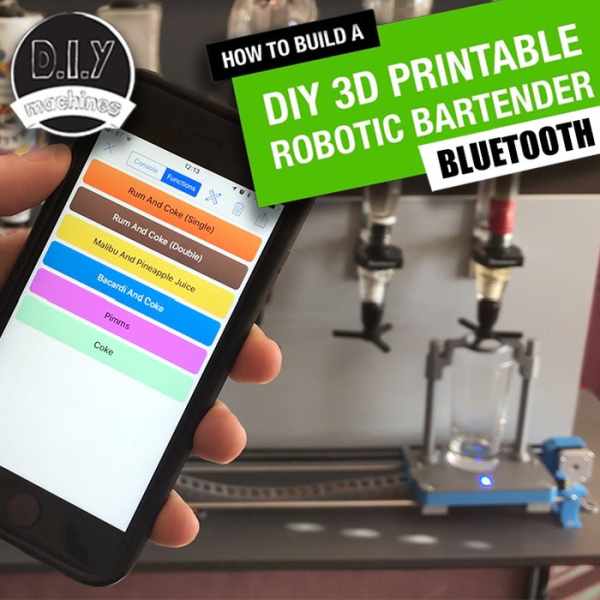
The aim of this project was to create a bar robot that was low cost and easy for anyone to write their own programme for. Many others out there soon get very expensive and often requires mains electrics – this is cheaper by design and runs entirely on 8 AA batteries. (Also makes it easy to take into the garden or a friends place).
List of items used in this project and where to find them (the links are Amazon affiliate links and financially support this channel at no cost to you)
Arduino Uno: http://geni.us/ArduinoUno
Motor driver: http://geni.us/ArduinoUno
Contact Switch: http://geni.us/ArduinoUno
Linear Bearings: http://geni.us/ArduinoUno
Stepper Motor: http://geni.us/ArduinoUno
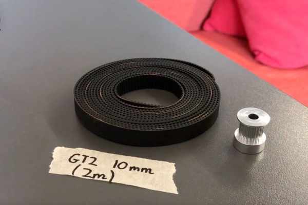
Timing Belt and Pulley (2m version): http://geni.us/ArduinoUno
Timing Belt and Pulley (5m version): http://geni.us/ArduinoUno
HM10 Bluetooth Module: http://geni.us/HM10Bluetooth
Step 1: Videos If You Prefer..
I’ve created a set of four step-by-step videos that you can follow along if you prefer to. I’d also recommend having at least a glance so you can see how this design functions.
Now for the written version…
Step 2: Creating a Base
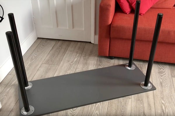
I used a piece of wood 18mm thick, 120cm long and 45cm deep. (The wood I used was 18mm MFC but any type would be fine as long as it is sturdy enough to be used as a table top). I then bought four table legs from IKEA which I screwed to it.
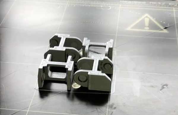
Step 3: Print and Assemble the Idler
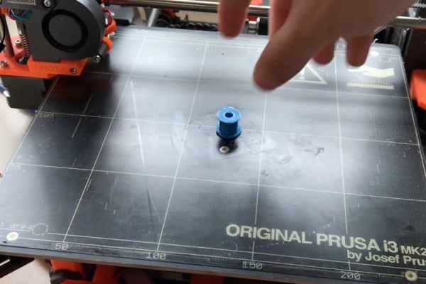
You’ll need to print the first two printed parts. You can find them over on the projects Thingiverse page:
The first two parts are called ‘idler.stl’ and ‘Rod_Clamp_V5.stl’.
Once both prints are complete you need to attach the idler to the rod clamp using a long M4 bolt and nut. Don’t over tighten this as it need to be able to spin freely.
You also want to insert a nut into the gap indicate (check the images) and part thread a longer bolt onto this. Later we will use this to help create tension on a timing belt (the rubber band with teeth on it used to pull the drinks paddle back and fourth along the steel rods).
This then screwing down onto the table top, 3 cm from the Left hand short end and 5cm from the front edge.
Step 4: Print and Assemble the Motor Mount
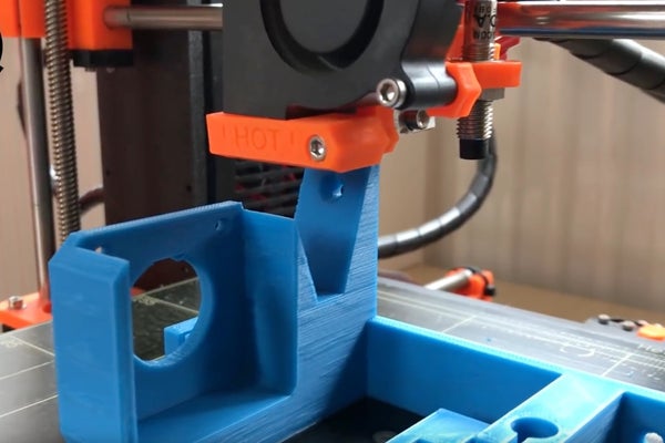
The file for the motor mount is ‘X_Axis_Motor_Mount.stl’
Once printed this one needs to be positioned 95cm opposite the idler assembly, and 5cm from the front edge. There are three screw holes for fixing this component to the table.
Step 5: Add the Steel Guide Rods
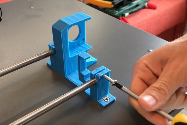
Now we can add two steel rods to the assembly. Mine are 1m long (this can be altered if you want your bar robot to have more or less optics – just remember to also reduce the space between the two components which we have already screwed down into the table).
Slide them into their holders and then use a M4 nut and bolt to tighten the grip of the printed part. You’ll need to fix these bolts into four places in total. One set at both ends of each rod.
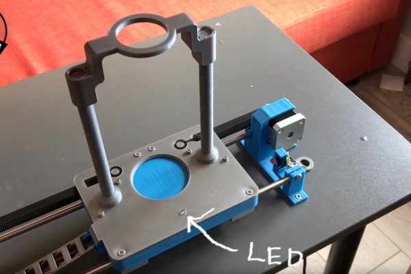
Step 6: Prepare the Status LED
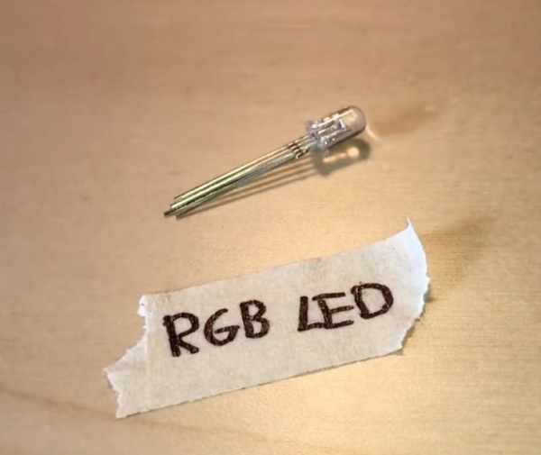
We will be using a RGB LED (this is one with Red, Green and Blue emitters all in one component which share a common cathode). You’ll need to solder a wire to each of the LEDs legs. The wires need to be 180cm or greater as they will have to run through the drag chain to our Arduino Uno. I’d recommend using four separate colour wires so that you can follow the wiring through later.
After you have soldered them together, wrap some insulation tape around each leg to prevent any short circuits.
Step 7: Assembling the Drinking Glass Platform/paddle – Part 1
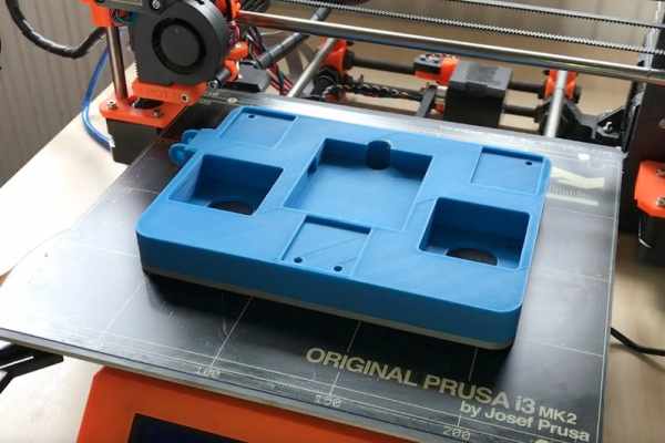
We now require another printed part, the drinks paddle. This is file ‘slider_base_v3.stl’.
Once printed, insert the LED through it’s hole from beneath and use some hot melt glue to fix it in position.
Now we can fit our two NEMA 17 stepper motors. Thread their leads though the cable outlet in preparation for connecting them – ensure you the get the cable the right way around (the end with the white connector. Pop them into their respective positions (see the image above) ensuring that their cable connections are both facing inwards. Turn the paddle over and we can hold these in place with some M3x10mm bolts. Put a couple of washers on each bolt before screwing in to help secure the motor.
You can then connect the leads for the steppers to the stepper. 🙂
Step 8: Assembling the Drinking Glass Platform/paddle – Part 2
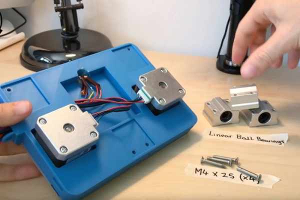
Now locate the three linear bearings on the underside and fix these in place with 4 X M4 x 25mm screws.
(This was a nice short step!)
Step 9: Building the Drag Chain
Now we need to begin to print pieces of the drag chain. This is where we will contain all our electrical wires between the Arduino and the moving paddle. You’ll need a fair few of them.
They snap together, it may be difficult to do so take your time. I used some pliers to help ‘close’ on part temporarily so it can fit between the dimples of the other.
Once you have joined them all together (you can always add more later if your chain is too short) thread the wires through them and attach one end to the paddle. Starting to look cool huh? 🙂
Step 10: Fixing Down the Drag Chain and Adding the Paddle
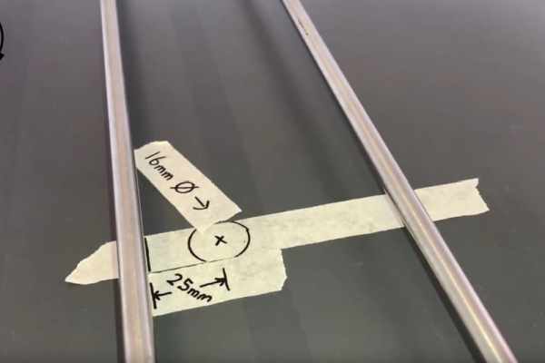
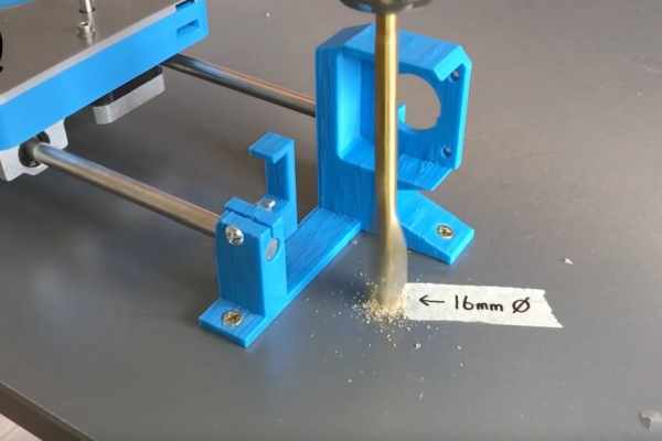
You’ll need to make a hole through the table top about 16 mm wide halfway along the distance of the steel rods. The centre of the hole needs to be 25mm back from the front rod. This is important so that the chain is not twisted in relation to where it exits the paddle.
Remove both rods from the right hand side of the barbot and thread them through the linear bearings. You need to do this carefully so as not to dislodge any of the balls from inside the bearings. When inserting the paddle make sure the short side with the chain attached is facing the hole we just drilled.
Now we can print and add a guide tube into the hole we drilled to help smarten it up a bit. The file to print is ‘Table_Tidy.STL’. You should be able to just push it into the hole – make sure that the flat edge is facing away from the paddle and chain we’ve been working with.
Thread all the cable down through the hole and then curl the cable chain under itself back towards the cable tidy as shown in the images. You can fix this in place against the flat edge of the cable tidy with a screw through the hole in the last piece of the cable chain.
The last image shows how your should look so far.
Step 11: Mounting the Contact Switch
We now need to make another 16mm hole at the right hand end, the location is not so important but near where I have drilled mine is ideal. Then we can print another tidy and insert it ‘Table_Tidy_End.STL’.
Use some glue to attach the end stop switch in the same orientation as mine. When you slide the paddle along it should make contact with the switch and close it.
Now we will solder three 1m cables to this switch. If you have three different colours it’s bet to use each of them so we can trace the wires with more ease later. Once soldered to the switch you can thread them though the adjacent cable tidy to keep them out of our way.
Step 12: Mounting the X Axis Motor
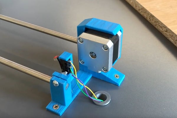
Position our final motor in it’s holder with the cable connector facing downwards.
Use two M3 x 10mm bolts to secure it in place from the other side.
Step 13: The Timing Belt Assembly
Take the pulley for the timing belt and attach to the shaft of the stepper motor for our X axis. (Don’t forget you can find a link to all the parts at the top of this guide). Ensure one of the grub screws is firmly attached to the flat side of the shaft.
Add the cable for this motor and thread the other end down through the cable tidy.
We can now take one end of the teethed belt and thread this thought the horizontal slot on one end of the paddle, push it through, wrap it around the pin so that the teeth come together and lock in the middle. Push this into the groove and this will hold it into place.
Take the other end, thread it around the pulley wheel on our stepper motor shaft and then bring it back to the paddle. You then need to thread it through the other horizontal slot and push it in until it appears out the other side of the paddle. Grab this and then again take it to the other end of the robot and thread it around our plastic idler wheel we printed.
Bring it back to the paddle one more time and thread it through the top horizontal slot. Pull it through and then trim it to length leaving enough to wrap it around the pin again and have it’s teeth interlock with itself in the narrowest part of the passageway.
You can then use the bolt on the idler end of our belt to add some more tension to the belt if it’s needed.
Step 14: Finish Z Axis
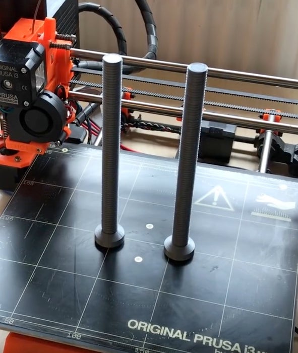
We’ll now require two threaded rods to be printed. That’s file ‘main_rod2.3.STL’. It’s worth taking the time to print these with a detailed layer height to help reduce any friction. You’ll also need to print ‘Dispenser_Paddle_V2.STL’ again use a detailed enough layer height. This part will also require supports.
Thread both of the rods into the paddle and then place them onto the shafts of the two stepper motors protruding from the raft.
Step 15: Wiring Up the RGB LED
The RGB LED we used has four legs on it which connect to the three colours and one common emitter (ground).
If you don’t have a note of which wire is connected where (or if you used four wires all of the same colour) we’ll figure out which is connected to what now. You’ll need an Arduino Uno, Mini breadboard, three 270 Ohms resistors and some jumper wires to do this.
We’ll first connect the 5v connection to the breadboard and then add one of the resistors to this. Then connect the ground from the LED to another section of the breadboard.
One by one, connect the other wires to the resistor and note which wire lights up which colour on the LED. For me it went like this:
Purple wire –> Red LED
Orange wire –> Blue LED
Red wire –> Green LED
Now we know which connect to what we can solder it to our motor shield.
Take four more wires, each about 15cm long and preferable the same colour as those used on your RGB LED and solder them all follows:
Matching colour wire for Red LED (in my case purple) to pin D9
Matching colour wire for Blue LED (in my case orange) to pin D10
Matching colour wire for Green LED (in my case red) to pin A1
Matching colour for ground wire (in my case yllow) to a GND pin.
Source: Arduino Robotic Bartender – 3D Printable & Bluetooth