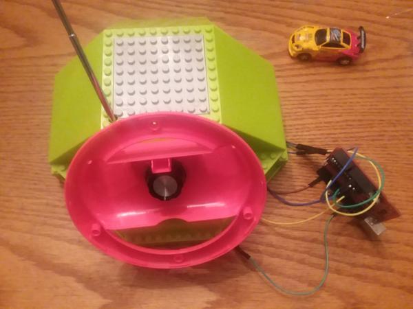
This is an Instructable of my Arduino RC car Wheel in which I took a cheap RC
car and made it so the Arduino could act as a wheel, controlling the direction it goes automatically. The Arduino RC car Wheel is my first original Arduino design I am proud to say even though the code and wiring is not very complex. Bear with me this is also my first Instructable, so I apologize ahead of time if I failed to explain something correctly or not enough.
PARTS-
RC Car
https://www.ebay.com/itm/Multicolor-Coke-Can-Mini-…
Arduino
https://www.amazon.com/Arduino-Uno-R3-Microcontrol…
Alot of Jumper Cables
https://www.amazon.com/Elegoo-EL-CP-004-Multicolor…
Potentiometer + Knobs
https://www.amazon.com/Gikfun-Knurled-Linear-Poten…
Polyester Capacitors
https://www.amazon.com/WINGONEER-0-33NF-Polyester-…
Tactile Switches for Extending Forward & Reverse Connections
https://www.amazon.com/WINGONEER-140pcs-Momentary-…
Breadboard
Mario Kart Wheel for the Switch
( Only if you want to go the route I went for making a casing )
https://www.amazon.com/AmazonBasics-Steering-Wheel…
KEEP IN MIND-
The RC car charges with the DC jack the Controller has, the battery doesn’t last that long.
Its a cheap Car, the On and Off switch actually started to move into its casing so I had to open the car and hot glue the switch so it wouldn’t move. I have gotten one of these that did not work right out of the box.
This is not a complex project, Someone could probably make it better and might even be able to replicate it with a better car, It was just an experience building project for me.
Step 1: THE CODE
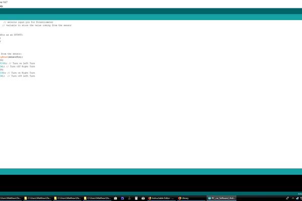
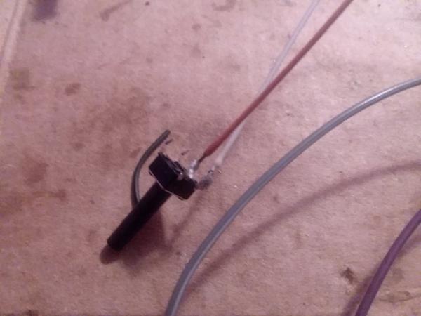
Upload the Code to an Arduino ( I used an Arduino Clone but I don’t think it matters ). Grab 6 Jumper Cables and a Potentiometer. Solder 3 cables to the Potentiometer’s terminals.
Step 2: BreadBoarding Prototyping
1. Plug the Middle Terminal Cable into Analog pin 0, Right Terminal Cable to 5 Volts, and Left Terminal Cable to Ground.
2. There should be 3 Cables left, Plug one into Digital pin 8 of the Arduino, Plug another into Digital pin 2, and the last one to the Arduino’s ground.
3. Now grab 2 LEDs and plug them into a breadboard, make sure they’re connected to Ground while they’re Positive pins are plugged into empty columns( not the Positive rows ), and now plug the Digital pin cables into the LED Positive columns( and connect the Ground cable to the Ground rail ).
4. Turn the Arduino on and Turn the Potentiometer, it should turn the LEDs off and on depending on what position it’s in.
FEEL FREE TO CHANGE THE CODE TO YOUR LIKING
Step 3: DISASSEMBLY OF THE MANIPULATOR
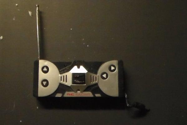
Grab a Screw Driver and Disassemble the RC Controller. Take a look at
the Circuit Board but be careful not to bend it or break off any the surface mount components.
Step 4: Switching the Controllers Power Source
You’ll want the RC controller to be powered by the Arduino instead of 2 AA batteries so
Desolder the wires that lead to the AA Battery Holder and Solder Male Jumper Cables in the same spots( B- and B+ holes ).
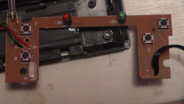
Step 5: Incorporating the Arduino Signals Into the RC Controller
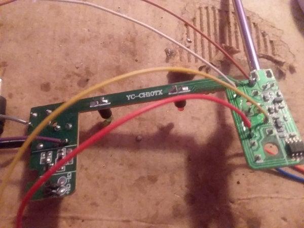
Look at the picture and solder 2 cables to the pins of Tactile switches Right and Left( The Grey and Purple Wires ).
Get 2 Film Capacitors( Also known as Polyester Capacitors ) and Solder them to tiny separate Protoboards( I just cut a corner of one and stuck em on ). The Reason for using Film Caps is that the Arduino still produces a voltage high enough when set LOW that activates the RC controller. So the Film Caps kind of act as resistors for a voltage coming out a digital pin when set LOW through the code.
Solder the Digital Pin cables to the ends of the Film capacitors, then Solder Right and Left cables to the Other ends of the Film capacitors.
Step 6: EXTENDING THE CONNECTIONS OF FORWARD & REVERSE
Get 4 cables and extend the connections of the Forward and Reverse Tactile switches. This is done by soldering one cable to the top left pin of a tactile switch and then soldering another cable to the bottom right pin of the same tactile, then soldering the ends of the cables to a separate tactile switch. Be careful and don’t accidentally Desolder a Surface Mount component, I made that mistake the first time and ruined the controller( Thank God these cars are only 8 bucks ).
Source: Arduino RC Car Wheel