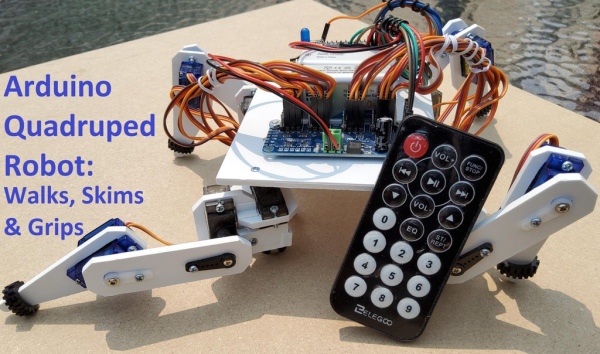
I made an Arduino quadruped robot “by-hand,” meaning without a kit or a 3D printer. It walks using a “long step” gait, which can be very smooth and natural looking. It didn’t quite come out the way I wanted though. However, to make my robot unique, I had the idea to create a skimming-type motion along the floor, similar to the way that boatman water beetles swim. In all my searches online, I have not come across a quadruped robot that has been programmed to move in this way, so this may be the first of its kind published online (?). The skimming motion is an awkward, jerky way to move, but is super fun and much faster than walking. Furthermore, it has allowed me to program a “gripper mode” with the front lets where the robot to be able to pick up small, light-weight objects. In the first video below, the robot walks then skims along the floor. In the second video the robot walks, then about halfway through the video it grips the garbage and disposes of it before skimming way.
This Instructable is not intended as a beginner project, so I assume you have some knowledge about using Arduino and uploading sketches, etc. That being said, I started this project when robotics was a new hobby, so the design and construction has been a trial-and-error process. If you have constructive feedback feel free to leave it in the comments at the end. Also, if you like the robot, please vote for it in the current Arduino contest!
Step 1: Overview of the Design
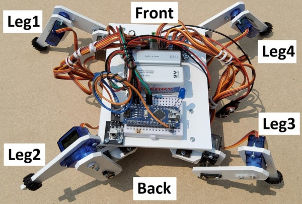
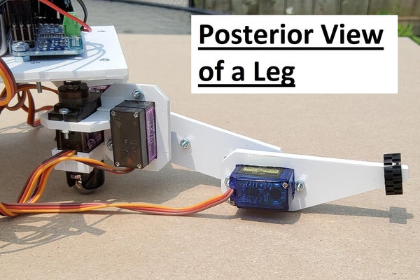
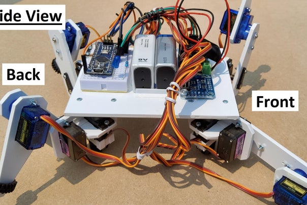
The legs are numbered: 1) front left of the robot, 2) back left, 3) back right, and 4) front right. Each leg has three parts with a servo motor to move each part. The three motors are named: hip, femur and tibia, and are numbered for each leg. For example, in the programming for the motors of leg 1, they are called “hip1”, “fem1”, and “tib1”. At the bottom of each hip motor is a small ½ inch caster to roll in the skimming motion.
The robot uses two 9volt batteries. One powers the Arduino Nano, which in turn powers a servo motor driver, and a receiver for the remote control. The other battery is used for the motors, which was light but provided enough voltage.
I used an infrared (IR) remote to control the robot. These are easy to use with pre-programmed code available on the internet, and has many buttons which made it easy to run all the different functions of the robot.
Step 2: Getting the Parts
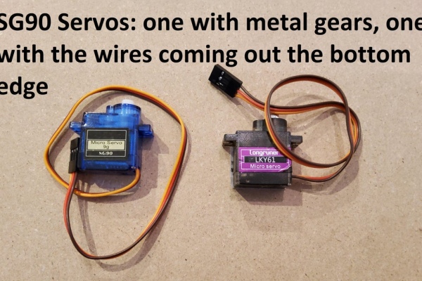
- Servos motors SG90 (x12) – with servo horns (included with the servo motors: 4 cross-shaped, 8 single lever type), and the included screws
- Nano microcontroller (x1)
- Mini 170-hole breadboard (x1)
- Pulse Wave Modulation (PWM) servo driver (x1)
- ½” Casters (x4) (link)
- Polystyrene plastic sheet – 3.2 mm thick (See hobby store link below)
- Polystyrene plastic sheet (just a scrap piece will do) (See hobby store link below)
- Polystyrene “L” shape plastic angle (4.8mm) (See hobby store link below)
- IR receiver module and IR remote control (a part from Elegoo kit)
- 9V NiMh rechargeable batteries (x2) and charger
- Connectors for the 9v batteries (x2) (link)
- M2 screws 10mm (x38) (link)
- M2 nuts (x60) (link)
- M2 screws 6mm (x14) (link)
- M3 screws 14mm (x2) (link)
- M3 nuts (x4) (link)
- 5mm LED (x1)
- 1000 Ohm resistor (x1)
- Jumper wires, male-to-female (x7) (a part from Elegoo kit)
- Optional: rubber Lego tires (x4) to add grip for the legs
Other Tools/Supplies:
- Arduino IDE (free software on the internet used to program the Nano)
- Mini USB cable (to program the Nano)
- Testors model glue (See hobby store link below)
- Hobby knife (x-acto knife)
- Set square
- Ruler
- Needle nose pliers
- Electric drill with 2mm drill bit and larger bits
- Twist hand drill – for holding small drill bits for drilling by hand
- Small screw driver for the M2 screws
- Sandpaper
- Soldering iron and solder (only if you have to solder the pins on the PWM/Servo driver, or on the Nano)
The body is made from 3.2 mm plastic polystyrene. I bought it from this store in Toronto, however you cannot search it on their website. A thinner sheet (e.g. 2mm) may be stiff enough without as much weight. In any case, polystyrene is easy to cut, drill and glue together so I recommend it for this project. The model glue melts pieces together which makes a strong bond.
Step 3: Make the Hip Frames Which Will Hold Two Motors Each
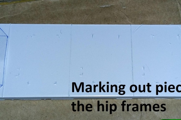
To make a stencil for the frame of the hip, first trace out the size of the bottom of the servo motor on paper. This represents the hole the servo will slide into, (although in the end you will need to make the hole a little larger than this). Next trace a larger rectangle so that there is at least 0.5 cm around the servo hole, but one side should be 1 cm. Using this stencil, a ruler and a set square, mark the outer edges of the frames in the polystyrene. Then with the stencil press the location all the corners through the stencil with the tip of your knife. Repeat until there are eight frames with the outer edge marked and the inner rectangle for the motor.
Cutting the polystyrene is very easy if doing straight lines. Use a ruler or set square score the cuts in the polystyrene with a few strokes of an X-acto knife. It does not need to be too deep. You should be able to bend the sheet by hand and it will snap along the scored line. It is not always a precise way of cutting plastic but it is fast and easy. For pieces that are too small to hold by hand, use the needle nose pliers to hold on, but cover the plastic with paper so the pliers do not leave marks. After cutting, touch up the edges with a knife or sandpaper to smooth out the bumps and ridges left by this cutting process.
Because the servo holes are within the plastic, these cannot be scored and snapped off. So, for each servo hole, use a ruler and knife to mark out a second smaller inner rectangle about 2mm inside the servo hole. With this double rectangle, the outer rectangle would be roughly the dimensions of the finished servo hole, and the smaller inner rectangle makes for a useful physical guide for making perforations. This is done by using a drill with a 2mm drill bit and making many holes all along the inner rectangle without damaging the outer rectangle. Then press the x-acto knife to cut the perforations to get a rough hole. Whittle the inside of the rectangle with the knife, widening it until it is large enough to allow the servo to just slide in without damaging the wires. This rectangle will need to be a little longer to prevent damaging the wires when you later insert the motors. (Note some servos have the wires coming off the bottom edge rather than the side of the casing which go in a lot easier.)
To fit two rectangles together at 90 degrees, cut a slot 0.5 cm deep into the outside edge of each rectangle. These are wide enough (3.2mm) to interlock two slots together. This will eventually turn the eight pieces into the four hip frames, but do not glue them yet. Make sure the depth of the slots is not so deep that the servo holes are blocked. Also, keep in mind that each hip frame is the mirror image of the two adjacent motors: legs 1 and 4, will have the fem motor gears facing forward, and the two back femur servos, legs 2 and 3, will have the gears facing backward. In other words, legs 1 and 2 are mirror images of legs 4 and 3, respectively.
When all the slots are finished, make the rectangles into hexagonal shapes by scoring the corners with the knife and using needle nose pliers to hold the corners and snap them off, one-by-one. Clean up edges with a knife and file. Now the hexagonals are glued to form the 4 hip frames double-checking the orientation so that there are two pairs which mirror image each other. To reinforce the joint of the hip frames, cut pieces of “L” shaped angle plastic and glue them along the joints.
After the glue is dry, slide motors in place without damaging the wires. If needed, make the holes for the servos larger. Then the 2mm drill bit with the handheld drill bit holder to mark where the holes will go. Repeat for all 8 motors in the hip frames, then drill these holes with the 2 mm bit and the electric drill.
Step 4: Preparing the Servo Horns – Drill 2mm Holes
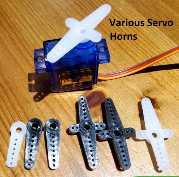
Servos usually come with a number of different shaped servo horns. Use a crossed-shaped horn to attach the hip motors to the main body. The two longer arms of the cross-shaped servo horn are not the same length. Use the second last hole on the longest arm, and the third last hole on the other arm. You should only need two screws to attach the cross-shaped horn to the main body. The holes in the horn are too small for the M2 screws so widen them with a 2 mm drill bit by hand. For each of the femur and tibia servos, use a horn with a single arm (eight total). The width at the end of these horns may also be too narrow to hold the M2 screw so use the second-to-last hole.
Step 5: Making the Tibia Pieces
There are lots of variations in other projects for the shape of the tibia piece. The ones for this robot are 2cm wide at the top and 7cm long. At the top of the tibia cut the rectangular holes for the servo leaving 0.5 cm of polystyrene on both sides and the top end. Use a ruler, knife and pliers, to score and cut the tapered bottom end of the tibia pieces, and to remove the two top corners.
Step 6: Making the Femur Pieces
The femur is the same width (2 cm x 7 cm) as the tibia. With a pencil draw a longitudinal line down the centre of the femur. This will be used to align the servo horns and marking the location of the screw which will secure the horns to the femur pieces. To do this, mark out on the femur piece where the centre of the gears of the tib and fem motors would go, about 1 cm from each end. Make a hole with a small drill bit and widen these holes with successively larger drill bits, until the circular portion of the horn can be inserted. Repeat so that each femur piece has two holes. Then one-by-one hold the horn aligned in place and mark with a 2mm drill bit through the horn where to drill the hole in the polystyrene plastic. Remove the horn and drill the 2mm hole. Later, when it comes time to mounting, a M2 screw will go though each horn, then the polystyrene, and the nut will be tightened from the other side onto the polystyrene.
Step 7: Making the Main Body
The main body is a single piece of 3.2mm polystyrene measuring 9 cm x 12 cm. The body is longer front to back, than it is wide. To mark and drill the holes for mounting the hip motors, place the hip motor into the hip frame and a cross-shaped servo without the screw. The hip motors are placed in the hip frame so that the gears of the front motors are not at the front of the main body, and the gears of the rear hip motors are not at the back. The two front femur motors face forwards and the two rear femur motors face backwards. Also, ensure the direction of the servo horns is consistent – with the longest arms point backwards for the front motors (1 and 4), and forwards for the back motors (2 and 3). With those three alignment points ensured, line up the edges of the hip frame with the edges of the main body. For example, the front and left side of the frame holding the motor hip1 is aligned with the front left corner of the main body. (Front and left side of the hip frame with the front and left side of the main body). With the servo horn in the correct orientation, hold it securely against the main body and remove the servo and hip piece leaving the horn in place against the underside of the main body of the robot. Mark the location of the two enlarged holes where the M2 mounting screws will go. Replace the horn and double-triple check 1) the orientation horn to the motor, 2) orientation of the hip frame, 3) alignment of the hip to the edges of the main body, and 4) location of the holes before drilling with the holes with a 2mm drill. On the top surface you can use a larger drill bit to carefully widen the opening to be able to countersink the screw, but this is not necessary.
Step 8: Step 7: Assembling the Legs
Centre the all the servos to 90 degrees. You can modify the Sweep sketch in the Servo example sketches in the Arduino IDE.
Now the fun part! Attach the two motors to the hip frame, with the four M2 screws and nuts. Remember the orientation of the hip motors in the hip frame, and orient the fem motors with the gears closer to the bottom. Then attach the cross-shaped servo horns to the hip motor with the mounting screw that comes with the servo. This is screwed through the top centre of the horn into the gear of the motor. Then to attach the hip motor to the main body, align the edges of the hip frame to the edges of the main body and with needle nose pliers to hold the M2 nut while you tighten the M2 screw from the top of the main body. The femur piece should be mounted straight out, parallel to the main body. Press the short single lever horns into the femur pieces and attach with M2 screws and nuts. I used 6mm M2 screws for the horns of the tib motors because the blue motors had less clearance under the horn and the end of a 10mm screw securing the horn would have contacted the case of the servo. Then the tibia motor should be mounted to the tibia piece so that the gears are closer to the top. Now the horns on the femurs can be mounted on the femur and tibia motors, which should complete the legs! Placing a small rubber Lego tire around the end of each leg will help with traction when the robot is skimming.
Step 9: Wiring the Components
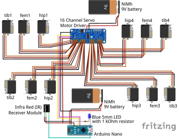
Insert the Nano into the breadboard. I attach male pins of a jumper wire to the end of the leads from a 9V battery connector. This way the red lead and black lead from the 9V battery is connected to the “Vin” and “GND” pins of the Nano, respectively. The PWM Motor driver is connected as indicated in the chart and in the Fritzing wiring diagram. The connections of all the jumper wires are as follows:
PWM Motor Driver: Nano:
GND…………………..GND
SCL …………………..A5
SDA …………………..A4
VCC ………………….5V
The motors are connected to the PWM/servo driver ensuring the 3 wires from the servos are oriented properly to each row of 3 pins on the motor driver. The pins for the servos on the driver are labeled for the 5V, ground (GND) and data wires. The wires of the servo are generally red for 5V, black or brown for ground, and orange for the data. With this orientation the motors are connected to the PWM/servo driver as follows:
Servo motor: …………3-Pin of PWM motor driver:
hip1 ……………………..0
fem1 …………………….1
tib1 ………………………2
hip2 ……………………..4
fem2 …………………….5
tib2 ………………………6
hip3 ……………………..8
fem3 …………………….9
tib3 ……………………..10
hip4 …………………….12
fem4 ……………………13
tib4 ……………………..14
Note: 3, 7, and 11 are not used.
The second 9V battery is connected via the connector wires to the screw terminal of the PWM motor driver, red lead to positive, black lead to negative.
The infrared sensor is connected with jumper wires to the Nano via the breadboard as follows:
IR sensor: ……….Nano:
Vcc ………………..5V
GND ………………GND
Data ………………D12
A light emitting diode (LED) is used to indicate when the robot is standing by for another command. Because the walking motions take some time. This helps because if you press the remote too early, then the robot will miss the command. And if you press multiple times in a row, the remote gives a “repeat” command which the robot is not programmed for. The LED is wired into the breadboard with the anode (long lead) of the LED connected to pin D13 of the Nano. The 1 kOhm resistor connects the cathode to the ground (GND) of the Nano.
Step 10: Attaching the Components to the Main Body
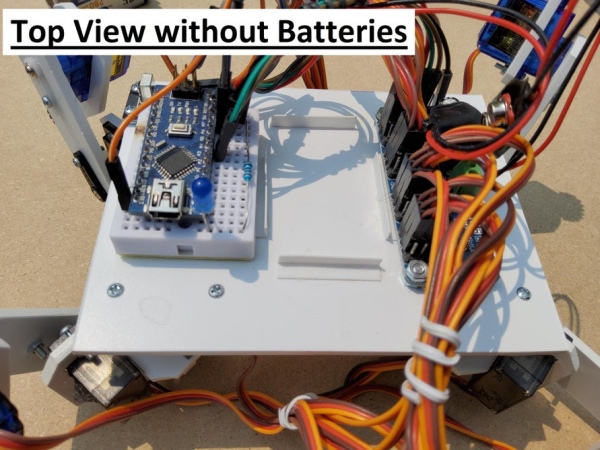
Place the breadboard with the Nano, PWM servo driver, IR receiver, and the two batteries on the top center of the main body to ensure things are centred and there is enough space.
The breadboard with the Nano is centered to the rear of the robot. When placing the Nano, be mindful that if you need to tinker with the programming, the mini USB cable will need to be inserted into the Nano while the legs are still able to move. Once you are pleased with the location, you have to be able to mount the breadboard. There is a double-sided adhesive pad on the bottom of the breadboard, but in case you want to move it in the future, you can use screws instead. The breadboard has two screw holes but 10mm M2 screws are not long enough to go through the breadboard and the 3.2mm polystyrene. So, with the breadboard in place, mark the location of the holes using a small 2mm drill bit. This means cutting through the double-sided tape and into the main body of the robot. Remove the breadboard and finish drilling the two 2mm holes. Then take the 10mm M2 screw from the underside of the body and secure it with a nut on top. The shaft of the two screws stick up from the main body. Place he breadboard on these screws to prevent the breadboard from sliding around, but allows the breadboard to be easily lifted out of place.
The PWM servo driver was centered at the front of the robot. Mark the location of the holes for drilling. The servo driver is held in place with two M3 screws and nuts. For each screw you can put a nut between the main body and the servo driver to give a bit of space.
Glue four small lengths of the “L” shaped polystyrene to hold the batteries in place so they would not slide around.
The IR receiver is placed at the back left, near leg two and is held in place with two 6mm M2 screws. Remember IR receiver must be “visible” to the remote, so nothing can obstruct the view of the receiver. Two M2 nuts can act as spacers and two nuts to secure the IR receiver.
Step 11: Attaching the Casters to the Bottom of the Hip Servos
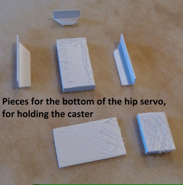
To attach the 1/2’” casters, a box is constructed to fit the bottom of each hip servo. The bottom of the box is a piece of the 3.2mm polystyrene the size of the bottom of the hip servo. Three (3) of the sides of the box are pieces of the “L” shaped angle plastic. These sit on the 3.2mm piece and the corners of the horizontal side are cut at a 45-degree angle to make tight corners of the box. (In the picture, you can see I roughened the surfaces to be glued before sticking them together, but this is not necessary because the glue melts the surfaces together.) At this point, centre a caster to the bottom of the box and mark the drill holes through the bottom into the inner-portion of the box. Use a larger drill bit in the box to be able to countersink the heads of the M2 screws. Countersinking will allow the servo to sit as deep as possible to the box. The fourth side of the box is a piece of thinner polystyrene which extends out about 0.5 cm from the side of the box to make a tab. It is taller than the other three sides, because this tab is used to mount a screw to the vertical portion of the hip frame. A small piece of the 3.2mm polystyrene is placed on this tab to make a snug fit. Four small pieces of the “L”shaped angle plastic were cut and glued to reinforce the box. Then use two 6mm M2 screws from inside the box and through the mounting holes of the servos. Use the M2 nuts and needle nose pliers to attach the casters to the boxes. Finally slide the box over the bottom of the servo. Make sure it is in as deep as possible, then drill a 2mm hole through the tab and the vertical potion of the hip frame and secure with a M2 screw and nut.
Step 12: Step 11: the Code
There are many tutorials on how to upload the code to an Arduino (Arduino IDE, YouTube, with Arduino kits, etc.) so I will not explain that. However, I will explain some of the highlights of the code. The code is far from perfect and is quite long, so I will not go through all of it. Much of it is based on the PWM/Servo driver example sketch from Adafruit (link), and the IR remote control tutorial from the Dronebot Workshop (link).
The code relies on three libraries as background programming. These are:
- IRremote.h
- Wire.h
- Adafruit_PWMServoDriver.h
The PWMServoDriver can be downloaded from the Adafruit link above. As the name implies, it controls the servo driver which controls the servo motors. The Wire library is a standard library that comes with the Arduino IDE software. The IRremote library can be found in the Library Manager of the Arduino IDE.
One of the variables in the code is “togglePosture” declared near the top of the code. This tracks of the mode the robot: walking, skimming, or gripping. When the robot is about to move, the Nano will check the value of togglePosture to determine what the current mode is. If necessary, it will run the appropriate function to change posture and then update the togglePosture variable to the new mode (skimming=0, or standing=1, or grip/skimming=2, or none of these=3). This allows the user to, for example, activate the “skimForward” function when the robot is standing. Since the robot is not in the skimming mode, the togglePosture does not equal 0. So, the robot will call the “skimPosture” function which will cause the robot to drop down to the casters, and then the value of the togglePosture variable will be updated to equal 0, before the robot skims forward.
Because of the orientation of the motors some are turning clockwise to flex up or go forward, and others turn counter clockwise for the same motion. So, for example, for tib1 and tib3, a value of 100 is fully flexed. However, for tib2 and tib4, a value of 600 is fully flexed.
For walking, the forward and back motions were meant to be smooth coordinated movements with more than one joint moving at a time. It requires a series of motions with the robot shifting its weight to keep the centre of gravity under three legs while the fourth leg is lifted and slowly moved. In order to do this, the forward and back walking functions are split up into several “for” loops in the code (similar to the programming of the “Sweep” example code for the Servo library if you have used it). For example, one of the first motions for walking forward is to shift the weight towards leg4. This has the following code:
for (tib2 = 400; tib2 < 500; tib2 = tib2 + 1) {
if (fem2 < 450) fem2 = fem2 + 1;
if (hip3 < 500) hip3 = hip3 + 1;
if (tib4 > 300) tib4 = tib4 – 1;
if (hip1 > 350) hip1 = hip1 – 1;}
pwm.setPWM(0, 0, hip1);
pwm.setPWM(5, 0, fem2);
pwm.setPWM(8, 0, hip3);
pwm.setPWM(14, 0, tib4);
pwm.setPWM(6, 0, tib2);
delay(delayTime);
}
In this section of code, the first line is: for (tib2 = 400; tib2 < 500; tib2 = tib2 + 1) {
To explain this line: the variable, tib2, corresponds to the position of the tibia motor on the second leg and starts at 400. This line also specifies that as long as the value of tib2 is below 500, the Nano will loop through the eleven lines of code over and over, but each time it will increment the tib2 value by +1. The next few lines of code are several “if’ statements, where fem1 and hip3 will also increase in position by a value of one each time through the loop as tib2 increases, and tib4 and hip1 will decrease by 1 each time.
The lines with “pwm.setPWM” are the functions that direct the PWM servo driver to advance the motors the new position indicated by the “for” and “if” statements. Because each motor position only changes by 1, the movement is only a small movement. By incrementing these variables one value at a time, the legs will move slowly and smoothly. Furthermore, because tib2, fem1, hip3, tib4 and hip1 are all affected, these five motors will move simultaneously, just like the robot was coordinating several joints at once.
The line, delay(delayTime), causes the Nano to pause before each loop of this code. The variable “delayTime” was defined at the very beginning of the whole code, like the togglePosture variable. However, this variable represents the duration of the pause in milliseconds. It therefore controls how fast the Nano goes through this section of code over-and-over again. The pause must be short enough that it does not appear that the motor stops between each incremented movement, otherwise it would move like the seconds hand on an analog watch. By using this pause between each cycle through the section of code the walking is purposefully slower and smoother.
When tib2 reaches 500, the “for” loop will end and the Nano will go to the next section of code (not shown here), which will orchestrate a different set of movements with different motors.
In contrast to the walking, the code for the skim and grip motions are meant to be much quicker, so the movements are not incremented in “for” loops like the walking. For example, near the beginning of the “skimForward” function is this excerpt of the code:
fem2 = 330, fem3 = 390; // femurs up
pwm.setPWM(5, 0, fem2);
pwm.setPWM(9, 0, fem3);
if (togglePosture == 0) {
fem1 = 375; pwm.setPWM(1, 0, fem1);
fem4 = 300; pwm.setPWM(13, 0, fem4);
}
delay(10);
In this code, the values of fem2 and fem3 are both changed so that those two legs will lift up. The two pwm.setPWM lines execute those two movements to the motors, no incrementing the movement, just one command so it will be sudden and quick. The “if” statement in this code is to check if the robot is in the “skim” mode in which case the next two lines (between the curly brackets {}) are executed which will also bring the front legs, legs 1 and 4, up as well. If the togglePosture variable was NOT zero, then the robot would be in the gripper mode, and so the two front legs are not used to move and so legs 1 and 4 will not be moved here. The delay(10) function delays the robot for 10 milliseconds to give the motors enough time to reach their new positions.
At the end of the full code, the loop() section is very short and quick, and is as follows:
void loop()
{
if (irrecv.decode(&results)) {
if (results.value != 0xFFFFFF) { //0xFFFFFF is the “repeat” command from the remote, so the robot will ignore it
digitalWrite(LED_PIN, LOW); // turn off standby LED
val = results.value;
irrecv.resume();
switch (val) { // Which functions to call when button is pressed, buttons were defined before the setup
case P: Pause (); break;
case Fr: forward(); break;
case B: back(); break;
case L: left(); break;
case R: right(); break;
case St: stand(); break;
case Lu: legsUp(); break;
case Ld: legsDown(); break;
case lt: legsTogether(); break;
case Eq: gripPosture(); break;
case La: legsApart(); break;
case Sf: skimForward(); break;
case Sb: skimBack(); break;
case Sr: skimRight(); break;
case Sl: skimLeft(); break;
case S: skimPosture(); break;
default: break;
}
}
}
digitalWrite(LED_PIN,HIGH); // turn on the standby LED just in case
}
The first line is: if (irrecv.decode(&results)) {
This line will call on the Nano to decode the IR signal from the remote control if one was received by the IR sensor.
In the line, “val=results.value”, the value of IR signal is recorded in the variable called “val”. This variable is then used in the switch function which compares “val” to the different cases, each of which corresponds to one of the movement functions. The Nano will run that movement function, then return in the code to the beginning of the loop section to decode the next IR signal.
You can download the current version of the code here:
Robot_WalkSkimGrip_July2021.inoDownload
Step 13: Controlling the Robot With the Infrared Remote Control
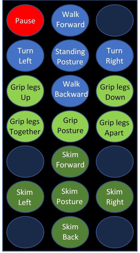
The actual remote can be seen in the first picture of this instructable. The buttons of the remote will cause the Nano to each run an individual function in the code (see the diagram of the remote and the functions). The button and the name of the function (in quotation marks) are as follows:
- ON/Off = “Pause” This causes the robot to drop to the casters and retract all 4 legs. Useful to unload the motors and therefore the battery
- Vol+ = “forward” The robot will stand if not doing so already and walk forward. This is a series of smooth movements of the legs.
- Rev << = “left” The robot will stand if not doing so already and turn to the left. This is a quick shuffle of the legs
- Play = “stand” The robot will stand if not doing so already
- FastForward >> = “right” The robot will stand if not doing so already and turn to the right. This is a quick shuffle of the legs
- Vol- = “back” The robot will stand if not doing so already, and walk backward. This is a series of smooth movements of the legs.
- Arrow up = “gripUp” For when the robot is in gripper mode, the robot will raise the level of the front legs
- Arrow down = “gripDown” For when the robot is in gripper mode, the robot will lower the level of the front legs
- 0 = “gripTogether” For when the robot is in gripper mode, the robot will bring the front legs closer
- EQ = “gripPosture” The robot will assume the posture for gripper mode. The front legs are retracted, and the back legs are out to either side
- ST/REPT = “gripTogether” For when the robot is in gripper mode, the robot will bring the legs further apart
- 2 = “skimForward” The robot will skim forward pushing itself with the legs out to the side. This is a quick push which can be done in the skimming mode or in the gripper mode
- 4 = “skimLeft” The robot will skim to the left with the legs out to the side. This is a quick push which can be done in the skimming mode or in the gripper mode
- 5 = “skim” The robot will assume the skimmer mode posture if not doing so already. All four legs will be straight out to the sides
- 6 = “skimRight” The robot will skim to the right with the legs out to the side. This is a quick push which can be done in the skimming mode or in the gripper mode
- 8 = “skimBack” The robot will skim backward pushing itself with the legs out to the side. This is a quick push which can be done in the skimming mode or in the gripper mode
Note: The following buttons are not used: Func/Stop, 1, 3, 7 and 9.
Well, that’s it. Thanks for your patience going through all of that. It was quite challenging to make the robot, especially the code. I found that depending on the state of the batteries, the positioning of the legs changes, so it is hard to troubleshoot because what works at one time gives slightly different results another. I am sure it would be even better with better servos, but I was still rather new to Arduino when I started this.
If you have questions, please feel free to leave them in the comments. There is more, but this Instructable is pretty long as it is. If you make the robot, have fun and let me know how it works! If you like the robot please vote for me in the contest! Thanks.
Source: Arduino Quadruped Robot: Walks, Skims & Grips