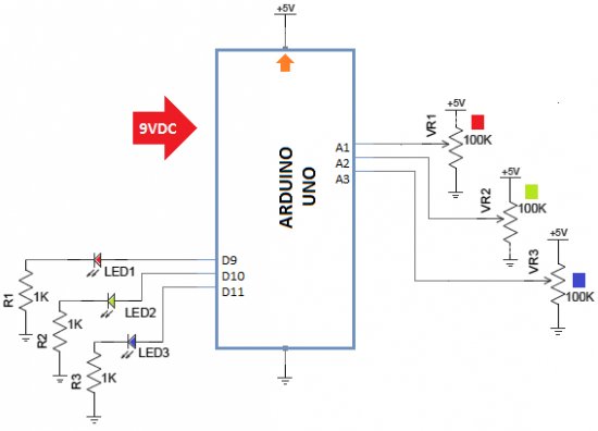
Looking for a simple circuit to control the light intensity of Light Emitting Diodes (LEDs) or similar lighting sources? Here is an Arduino based circuit with three independent pulse width modulated (PWM) channels to fulfil your requirements! Just follow the schematic diagram to complete the construction, and use any standard 9VDC Arduino power source to energize the system. Here, for demonstration, three different color LEDs (Red, Green and Blue) are used. You can control the brightness of these LEDs using variable resistors VR1, VR2 and VR3 respectively.
Parts Needed
- Arduino UNO board – 1
- 5mm LEDs Red, Green, Blue – each 1
- 100K Variable resistor – 3
- 1K ¼ w Resistor – 3
Arduino Sketch
- //MULTI-LINE LED CONTROLLER using PWM
- //T.K.Hareendran
- //www.electroschematics.com
- // Analog inputs connected to the variable resistors
- const int knobPin1 = 1; //Red LED control
- const int knobPin2 = 2; //Green LED control
- const int knobPin3 = 3; //Blue LED control
- // PWM outputs connected to LED driver circuits
- const int drivePin1 = 9;//Red LED drive
- const int drivePin2 = 10;//Green LED drive
- const int drivePin3 = 11;//Blue LED drive
- // initial value for the variable resistors
- int knobValue1 = 0;
- int knobValue2 = 0;
- int knobValue3 = 0;
- void setup() {
- // set the drive pins as output:
- pinMode(drivePin1, OUTPUT);
- pinMode(drivePin2, OUTPUT);
- pinMode(drivePin3, OUTPUT);
- }
- void loop() {
- // read the variable resistors, convert it to 0 – 255
- knobValue1 = analogRead(knobPin1) / 4;
- knobValue2 = analogRead(knobPin2) / 4;
- knobValue3 = analogRead(knobPin3) / 4;
- // use the data to control the drive:
- analogWrite(9, knobValue1);
- analogWrite(10, knobValue2);
- analogWrite(11, knobValue3);
- }
 Enhancement Ideas
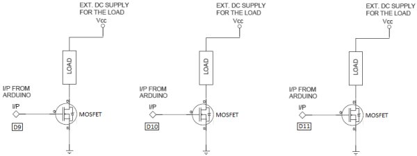
Here, the three LEDs are directly connected to Arduino pins with independent current limiting resistors (R1, R2 and R3) which is enough for a basic model. But if you wish to control Hi-Power LEDs (or similar loads) additional driver circuitry is necessary. For this purpose try the following modification with your working prototype. This is a where a Power Mosfet comes in. With the help of the Power Mosfet, we can use the low voltage output from the Arduino ports to control high voltage/current loads -the popular “12V LED strips”- for instance. Remember to power the output load(s) from a worthy external dc power supply. Part number of the Mosfet is not very critical. Always try to use a type which can safely handle the load current (for example IRF510 or IRF520 MOSFET).
For more detail: Arduino PWM Led Control