I recently had my kitchen updated and knew that lighting would ‘lift’ the look of the cupboards. I went for ‘True Handless’ so I have a gap under the work surface, as well as a kickboard, under cupboard and on the top of the cupboards available and wanted to light them up. After looking around I couldn’t find exactly what I wanted, and decided to give it a go making my own.
For the lighting I chose single colour, warm white LED strips (the waterproof type with a flexible plastic coating for protection).
For the wall cupboards, as they were flat on the bottom, I chose some very low profile lights and routed the cable inside the cabinet and around the back (inside the cupboards I cut a groove using a Dremel for the cable, then filled it back in once the cable was inside, so there is no sign of it).
BUT… I didn’t want a large switch, and did want a premium look to how the lights appeared, so after looking around and finding some fade up/down switches, and one Alexa-enabled one, I still couldn’t find one which could run all of the lighting and still make it look good, so I decided to make my own.
My project therefore was to produce one device which could power all four of the lights, with a staggered, fast fade up from a passive sensor – keep on until I leave the kitchen and either a switch to ‘force’ it to stay on, or if I leave the kitchen to fade off after a predetermined time if it doesn’t see anyone.
(And it didn’t cost much more than a single pre-built unit off amazon – with spares!).
Here is a video of it in action
Step 1: Parts
I’ve got a list of the parts I used from Amazon below. Feel Free to click the link to purchase them, but if you have similar items hanging around, use them!!! Note that some of these are ‘multiple’ items so you should have spares enough for making ones for friends and family, or just for other projects – but they are so inexpensive that to buy one off is often offset by carriage charges anyway…..
Parts for this project:
Full Arduino set (Note: not required but contains lots of things for future playing with!): https://amzn.to/2VD8dMb
Arduino NANO (Used inside the box): https://amzn.to/2KziW9A
PIR Sensor: https://amzn.to/2WUyZjs
LED Light Strips: https://amzn.to/2P5t3kP
LED Driver (Power supply): https://amzn.to/2UNWgWO
MOSFET boards: https://amzn.to/2WYOVB9
Push to make switches: https://amzn.to/2KFuDLZ
Black box for containing the Arduino and MOSFETs: https://amzn.to/2UaMn18
White box for sensor and switch: https://amzn.to/2UELqCD
Connecting wire from components to the LED strips: https://amzn.to/2VCt7uO
2.1mm plugs and sockets: https://amzn.to/2D8FS98
Wire for connecting Arduino to other components: https://amzn.to/2KAxHbQ
Thermal heatsinks (for MOSFETs) : https://amzn.to/2P1R4Jt
Thermal double-sided tape: https://amzn.to/2UGSyhK
Heat shrink sleeving https://amzn.to/2Dc6lD3
Step 2: Technology and How It Fits Together
To make this, first, we need to make the circuit…
So to start with, I used a bread-board and a full sized Ardiuno Uno. Having never used an Arduino before, I bought a package including a third-party Uno and a whole kit of parts (which after this, I will make use of for other projects). You obviously don’t need to do this if you are just following along for this project, but it’s a good idea if this might get you to build other things too.
The Bread-board allows you to just push wires and components onto a plastic board to let you test your design of the electronic part.
I put it together with a couple of red LEDs, and this allowed me to check how the fading part of the program worked (I temporarily set it up to time out after 10 seconds so I could see the effect of the staggered fade in and out). The way this works is that LEDs are instant on/off (unlike traditional bulbs), so you don’t need to put in a variable voltage – you can actually switch them on and off so fast that they look like they are not as bright. This is called Pulse Wave Modulation (PWM for short). Basically, the longer you keep them ‘on’ for, the brighter they get.
NOTE: once I wired up the actual light strips, the current draw from each of the complete strips causes them to be a little less bright AND they fade slightly differently – thus, I made the program with some configurable settings)
Although you can purchase small plug in power supplies to directly drive the LED strips, as I have four of them, I decided to purchase an LED driver (basically a power supply with a higher current output). I over-rated this as I didn’t’ actually check the real current draw until it had been built (as I was doing this all before the kitchen was installed). If you are retro-fitting this to an existing kitchen (or whatever you are using this for), you can measure the current draw per strip, add the values together and then choose a suitable LED driver (the next power rating up).
After breadboarding it, I realised the current draw from the lights would be too high to drive directly from the Arduino, so for the real unit I used some MOSFETs – these basically act like a relay – if they get power (from the low power side), they then switch on the connection on the high-current side.
I cheated here – I could have just bought the actual MOSFETs but there are some already mounted to small circuit boards available, together with screw connectors and cute little SMD LED lights on the board so you can see their status. Save time on soldering? Hell yes!
Even with MOSFETs, the maximum rating of the length of the LED strips was still drawing a few AMPs, and the MOSFET recommended to add a heat-sink to help keep them cooler. So I got some small heatsinks and used double-sided thermal tape to stick them onto the metal part of the heatsink. At full power, they still get hot, but after adjusting the maximum brightness in my program (the LEDs were TOO bright), I found that the MOSFETs don’t run hot anyway but it’s still worth adding them to lengthen the life of the components or if you do choose a brighter level than I did.
The Sensor also was available already packaged on a small circuit board, and this includes all of the support circuitry, as well as a couple of Jumpers (small pins with a link, which you can switch between positions to choose different options) and a variable timeout. As we are using this to trigger our own timer, we can leave them in the default position.
I added a small Push to Make switch near the sensor to allow me to ‘switch on’ the lights continuously and switch them off with a second press. This was the component I had the most issue with as a combination of things meant that the Arduino often thought that the switch was being pressed, so it would turn the lights on and off at random. This seemed to be a combination of noise within the Arduino, length of the cable, noise on the Ground/0V line, and that the connections within switches are noisy so they need to be ‘de-bounced’. I played with a few things, but ultimately settled on making the program check I was pressing the button for a few milliseconds – basically de-bouncing, but also ignoring any noise.
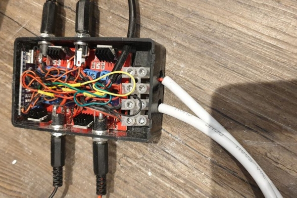
For the real unit, I found a small, unobtrusive box to house the sensor and push switch, and another that fitted all of the MOSFET boards and cables. To make things easier, I bought some two-core cable that could carry the current (and marked one cable for easy identification) and ran this around the kitchen to the start points of each of the light strips. I also bought some sockets and plugs, which allowed me to terminate the cables on a plug, and installed the four sockets in the larger box. This way I could re-order the light strips so they start from the kick-board, through the handles, under cupboard and over cupboard lights simply by unplugging them rather than changing the code.
This box also handily fitted an Arduino NANO (again a third-party board for less than £3) at the top. To get the small connections out of the NANO and to the MOSFETS etc I used a variety of coloured single-core cable (I used one with heat-proof insulation but you don’t need to). I still used the higher-current rated two-core cable from the MOSFETs to the sockets.
To drill out the boxes, I luckily had a pillar drill available, but even without it, you can drill a pilot hole with a smaller drill bit and then widen the hole to the size you need using a stepped drill bit ( https://amzn.to/2DctXYh ). This way you get neater, more controlled holes, especially in ABS boxes.
Drill out the holes as per the diagram.
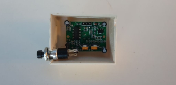
The white box, I marked the position of the sensor and where the white fresnel lens lay. Then once I found where the centre of this was, I drilled a pilot hole and then used the larger stepped drill bit to widen it (you could just use a ‘wood’ drill bit of that larger size). I then had to sand the hole a little larger BUT I didn’t push all of the fresnel lens through the hole – by keeping the hole smaller, it doesn’t make the sensor so ‘visible.
You will also find on the white box that there are a couple of lugs that stick out the side to allow you to screw the box to a wall, etc but I cut these off. I then widened the little cutout in the box designed for a cable on one side to fit the larger 4 core cable I used, and the other side of the box I widened it to fit the switch (see picture).
Step 3: Wiring It Up
See the attached wiring diagram.
Basically, you can use push-on connectors and then solder in the pins that come with the Arduino, or as I did, just solder directly to the pins on the board of the Arduino. As with any soldering job, if you are inexperienced, take a look at Youtube videos and practise first – but essentially: 1) Use a good heat (not too hot and not too cold) on the iron and make sure the tip is not pitted. 2) Don’t ‘load’ the solder onto the tip of the iron (although it’s good practise to ‘tin’ the end when you first start then wipe or knock off the excess – practise touching the tip of the iron onto the component and shortly afterwards touch the solder to the tip and the component at the same time and it should ‘flow’ onto the board. 3) Don’t overheat the components (IMPORTANT!!!) – if it doesn’t seem to be flowing, leave it to cool and try again in a while, and also don’t work on the same area too long. 4) unless you have three hands or have experience holding chopsticks, buy one of those Helping Hands things to hold the components together (eg https://amzn.to/2VFJJC4 ).
To make life easier, I also de-soldered the 3-pin connectors on the MOSFET boards. To do this, melt some solder onto the existing solder connection to help it flow again, then use a pair of pliers to pull the pins through whilst the solder is still molten. It helps if you have a de-solder pump or wick to draw the molten solder away before you pull the component out (eg https://amzn.to/2Z8P9aT ), but you can do without it. Similarly, you can just solder directly to the pins if you want to (it’s neater if you wire directly o the board though).
Now, take a look at the wiring diagram.
Take a piece of the fine single core wire and take a little of the insulation off the end (I find the rolson strippers and cutter https://amzn.to/2DcSkom good) then twist the wires and melt a little solder onto them to hold them together. Push the wire through the hole in the board and then solder the wire into place.
Continue this for all of the wires onto the Arduino that I have listed (use the number of Digital pins you need – I have 4 sets of lights but you can use more or less). Ideally use coloured cable that matches the use (e.g. 12V Red, GND black,etc).
To make things neat and prevent short circuits, I recommend sliding a little piece of heat shrink sleeving ( https://amzn.to/2Dc6lD3 ) for each connection onto the wire before soldering. Hold it far away whilst you solder, then once the joint is cool and after testing everything, slide it onto the connection and heat it with a heat gun for a few seconds. It shrinks down to make a neat joint.
NOTES: I read somewhere that there is some crosstalk between some of the pins on the Arduino D12 or D8. To be safe, I used D3 for the fourth output – but if you want to try others, feel free, just don’t forget to update it in the code.
Cut the cables to a reasonable length to fit inside the box, then cut and tin the ends again. This time, solder the cables to the MOSFET boards on the pins as shown. Each digital output (D9, D10, D11 and D3) should be soldered to one of four boards. For the GND outputs, I brought them all together and joined them with a blob of solder – not the neatest way, but it’s all hiding in a box anyway….
Arduino to MOSFETs
The input voltage I wired the +12V and GND in the same way, and put them and some short lengths of the 2-core cable into a Chocblock. This allowed me to use the Choblock as a strain relief for the incoming power from the LED driver/PSU and also allowed the thicker 2-core cables to be more neatly joined up. I initially tinned the ends of the cables but found they didn’t fit well within the connections on the MOSFET boards so ended up cutting off the tinned ends and they fitted better.
I took some more, 4 cm lengths of the 2-core cable and soldered these to the 2.1 sockets. Note that these have three pins on them and one is used to provide a feed when a connection is removed. Use the connection for the inner pin (12V) and outer (GND) and leave the third pin disconnected. Then put each cable through the holes in the side of the box, add a nut, then insert them into the MOSFET connector output terminals and tighten them up.
Connecting the Sensor
Using some four-core cable, cut a length long enough to travel from where you are hiding the PSU and box to where you are looking to place the sensor (make sure this is a location that will catch you as you walk into the area, but not tripping when someone walks by in the next room!).
Solder the wires to the pins on the sensor board (you can remove the pins if you prefer), and using a short length of cable (black!), wire a link cable to continue the GND cable to one side of the switch. Then solder another of the wires from the 4-core cable to the other side of the switch.
Place the sensor and switch into the white box, then route the cable around your room and then push the other end of the cable through the hole in the black box and solder the wires to the correct pins on the Arduino.
Place a small cable tie around the cable just inside of the box to help prevent this cable getting pulled and damaging your connection onto the Arduino.
Power
The LED Driver (Power supply) I bought had two output tails – both of which had 12V and GND out, so i used both of these and split the use so that 2 x LEDs went through two of the MOSFETs and were powered from one of the power supply outputs, and the other 2 LEDs from the other output. Depending upon the load from the LEDs you are using, you may have chosen a different power supply and only have one output.
Thus, my box has 2 x holes where the cables from the Power Supply enter, and I then put a Chocblock inside to make the connection and also to provide strain relief.
Step 4: The Arduino Program
The program (attached) should be relatively self-explanatory and I have tried to provide comments throughout. Please feel free to amend it for your own project requirements.
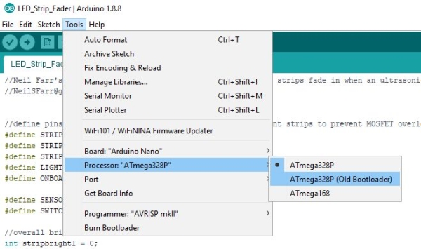
IMPORTANT: I set this up originally on a kit of parts and an Arduino UNO. If you then use of of the Arduino NANO boards, the bootloader on them is likely to be older. You don’t need to update this (there is a way to do this, but it isn’t needed for this project). All you need to do is make sure you choose Arduino NANO in Tools>Board, then also choose the correct one in Tools>Processor. Once you choose the COM port, you can also choose to see what’s happening if you connect to the serial console (Tools > Serial Monitor).
This is my first Arduino project, and I was pleased that it was really easy to download and install and use the Arduino programming tools (the thing that lets you type in programs and upload them to the board). (download the IDE from https://www.arduino.cc/en/main/software )
Simply by plugging the board into a USB port, it appears as a device you can upload a program to the board and the code runs!
How the code works
Basically there is a bit of setup a the top where I define everything. Here you can change the pins you are using for the lights, the maximum brightness of the lights (255 is max), how quickly it takes to fade up, and how quickly it fades down.
There is also an offset value which is the gap between one light fading to the next – so you don’t need to wait for each one to fade in – you can begin the next fade before the previous one has finished fading.
I chose values which work for me, but please feel free to experiment. However: 1) I wouldn’t advise turning the max brightness too high – although it works, I feel the lights are too bright and unsubtle (and, with a long string of LEDs, the additional current makes the MOSFETs get hot – in which case change the box for a more ventilated one). 2) the offset works for the current values, but due to the way LEDs don’t increase their brightness in a linear way based upon the power applied, you may find you also need to adjust the other parameters until you get a good effect. 3) In the fade up routine I have set the maximum brightness of my under-counter lights to max out at 255 (they draw less current so don’t overheat the MOSFETs and also I want to see what I am cooking!).
After the setup part, there is one big loop.
This starts with a flash or two on the onboard LED (so you can see it’s working, and also as a delay to give you chance to walk out of range of the sensor). The code then sits in a loop, waiting for a triggered change from the sensor.
Once it gets this, it invokes the TurnOn routing, where it counts up through 0 to the total value of all of the 4 devices at the chosen maximum value, increasing by the amount you specified in the FadeSpeed1 value. It uses the constrain command to prevent each output going larger than the maximum brightness.
It then sits in another loop, resetting a value if the sensor is triggered again. If this isn’t reset, then when the Arduino’s timer hits this point, it breaks out of the loop and invokes the TurnOff routine.
At any point during the ‘on state’ loop, if the switch is pressed for more than a few milliseconds, we flash the lights to confirm and then set a flag which causes the timer value to always get reset – thus the lights never fade out again. A second press of the switch causes the lights to flash again and for the loop to exit, allowing the lights to fade out and for it to reset.
Source: Arduino Powered, Sensor Controlled Fading LED Light Strips