This instructable will help you to build an Arduino Binary Clock. The orignial idea for this instructable was designed by Daniel Andrade. My instructable uses surface mount components, but can easily be adapted to through-hole components if you wish. You can follow my other Instructable for Building Your Own Arduino to get started.
I would encourage you to give the surface mount an attempt however as this project is a great way to begin learning to solder surface mount components.
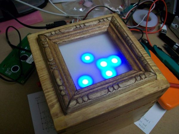
For my clock, I have the display set on the top of the container. I use it on my workbench which I am usually standing at, so this way is easier to see. It also creates a nice luminous effect when the lights are down low or off, casting the blue color upwards into the room.
You can select a container to your liking and place the clock face how it best fits your needs.
Step 1: Component Shopping List
Below is a list of all the items that you will need in order to complete this project. I have tried to include places where you can order from as well as optional components that you may want to pick up.
This list is for surface mount items. If you decide to go with through-hole components, the resources I have listed all sell them as well and you can just do a search on the component.
What You Need:
- ATmega168 with Arduino Bootloader – Available at FunGizmos for $4.00
- 10K Resistor – Available at Jameco – Cost 0.01 (ea./ 100 for $1.00) Item # 1877832
- 220 Ohm Resistor – Available at Jameco – Cost 0.01 (ea. / 100 for $1.00) Item # 1878149
- 22pF Capacitor – Available at Jameco – Cost 0.06 (ea. / 100 for $6.00) Item # 1856783
- 10uF Capacitor – Available at Jameco – Cost 0.12 (ea. / 10 for $1.20) Item # 1858797
- Pushbutton Switch – Available at Jameco – Cost .35 ea. Item # 2076236
- LM78L05AC Voltage Regulator – Available at Jameco – Cost .39 ea. Item # 902186
- 13 LED’s. I used Blue, but you can use any color. Available at Jameco – Cost .25 ea Item # 2046441
- 16MHz Crystal – Available at SparkFun.com – Cost 1.50 ea SKU: COM-00536
- DC Power Jack Connector – Available at SparkFun.com – Cost 1.25 ea. PRT-00119
- If you don’t already have one, an Arduino Board. Available at SparkFun.com – Cost 29.95 DEV-00666 or Build Your Own Arduino
- PC Board (Perf Board/Proto Board) – Available at Radioshack – cost varries.
- Optional Protoboard – Available at Wright Hobbies – Cost 3.99 Item # PB400. I love these!
- Project Container. This will be used to house your clock. I went to Hobby Lobby craft store and picked up a cheap wood box for $1.99, and some scrap trim molding from Lowes for .25
- Translucent Acrylic – I picked up some white translucent acrylic from a local shop which cost $1 per pound.
- x2 SPDT Pushbuttons – Available at RadioShack -Cost $3.99 – Catalog #: 275-1549
Step 2: 8421 Binary and 24 Hour Time
First, lets take a look at how to understand the 8421 Binary system. Your clock is going to have two columns for the “hours” and two columns for the “minutes”.
We are using a 24 hour time system.
With that said, if it were 8 AM, the time is 0800 hours and if it were 8 PM, the time would be read as 20:00 hours. In US Army basic training, when you first learn this time system, they taught us to just count backwards by 2 for PM times. So for example, if I was told to be in formation by 2100 hours. In my head I was thinking 2100 – so 1, 0, 9 and knew they meant 9 PM.
Or if we were off work at 1630 hours, in my head I was thinking 1630 – so 6, 5, 4 and knew the day was over at 4:30 PM. I hope that makes sense, I felt the need to explain for anyone who is not use to telling time with this method.
Looking at the 8421 Binary Example image, in the first column of the hour leds, if the first led was lit up, its value would be worth 1 and in the second column if the 4th(top) led was lit, its value would be worth 8. Therefore you would have 18.
Now with the minute leds, lets say the first column has the third led and the first led lit up. This value would be 4+1=5. The second column, third led is lit up would give a value of 4. So together you would have 54.
The overall time would read as 18:54 which would be 6:54 PM
Look at the second image example. The time is 21:37
Examples Images from Daniel Andrade
Step 3: Creating the Arduino Binary Clock PCB
You have a few options with this step. You could use your Arduino board and run all the components to it. This option however, you wont have access to your Arduino as long as you are using the clock 🙁 so you would have to buy another one.
You can Build Your Own Arduino onto a piece of Protoboard, and then run the connection wires to a seperate protoboard that has the LED’s on it. This was the method that I used for my first clock design.
A better approach would be to etch your own copper PCB. The second clock that I designed I went with this method. There are pleanty of Instructables on how to do this. Since this method requires more equipment, I am going to keep with the first clock design for instruction purposes. Later or on your own you can research other methods if you would like to attempt etching your own PCB.
Once you have the protoboard that will be used as your Arduino completed. Use your actual Arduino board, and upload the sketch supplied at the end of this tutorial. Pop that chip out, and place it in the protoboard Arduino.
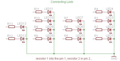
The resistors and leds will be connected from the second protoboard, down to your designed Arduino board. Follow the attached schematic with this step.
Arduino Pin 1 connects to Resistor 1 which connects to LED 1, which connects to GND.
Arduino Pin 2 connects to Resistor 2 which connects to LED 2, which connects to GND.
* repeat this process for all 13 resistors, pins and led’s.
SOLDERING TIP.
Place a tiny and thin layer of solder onto the area that you are going to be soldering to first, then with one hand holding the soldering iron, and the other using a pair of tweezers, place the component onto the area to be soldered to. Hold it down with the tweezers, and then reheat the solder. Keep pressure applied with the tweezers and move the solder iron away. Now you can let go with the tweezers and the part will be connected into place. More Instructables for soldering.
- ATmega168 with Arduino Bootloader
- 10K Resisto
- 220 Ohm Resistor
- 22pF Capacitor
For more detail: Arduino Powered Binary Clock