Summary of PCB Quadrotor (Brushless)
This article details the design and construction of "4pcb," a 138-gram micro quadrotor where the PCB serves as both the structural frame and electronics motherboard. The build utilizes an Arduino Pro Mini for control, a Pololu MinIMU-9 for sensing, and integrated Toshiba motor drivers to eliminate external ESCs. The project emphasizes custom EAGLE board design, surface-mount soldering, and specific vibration mitigation techniques for the IMU and motors to ensure stable flight.
Parts used in the 4pcb:
- HXM1400-2000 Brushless Outrunner Motors
- Toshiba TB6588FG Motor Drivers
- Arduino Pro Mini 328 Controller
- Pololu MinIMU-9 IMU
- XBee Series 1 Radio
- 3S Lithium Polymer Battery
- 4x2.5 and 4x2.5R Propellers
- Aluminum Standoffs for Landing Gear
- Heat Shrink Tubing for Motor Protection
- Double-sided Foam Mounting Tape
Quadrotors are the new Segway’s: a mesmerizing, somewhat magical, self-stabilizing platform that every tech person wants to have. You can’t ride a quadrotor (well, maybe you can), but they do fly, and you can build one yourself from scratch!
I helped with a previous quadrotor build (Instructable here), and after flying it I decided I wanted to make my own. I had an idea to make a miniature one comprising a single printed circuit board that is both its structural frame and its electronics motherboard. The end result was “4pcb”, a 138-gram micro quadrotor. I designed it in EAGLE, soldered it, and tested it over the course of a few months. Here’s some video of it flying, after a lot of control tuning (see Step 13) and practice:
More flight video in the final Step!
The idea of making a PCB-based quadrotor isn’t unique (see links below for other examples), and 4pcb definitely isn’t the smallest (see the Picopter Instructable for a really tiny one). But I think it strikes a good balance between size, cost, buildability, and flyability. It’s also one of the only PCB quadrotors with integrated brushless motor drivers, so there’s no need to wire up external ESCs. And it runs on XBee digital radios, so there’s no RC receiver or servo-style wiring.
4pcb Specifications:
Size: 6.50″ (165mm) motor center-to-center distance, diagonally
Battery: 3S (11.1V), 370mAh, 20-40C Lithium Polymer
Motors: HXM1400-2000 “hexTronik 5gram Brushless Outrunner 2000kv”
ESCs: Toshiba TB6588FG “3-Phase Full-Wave PWM Driver for Sensorless DC Motors”
Props: 4×2.5 (2), 4×2.5R (2)
Controller: Arduino Pro Mini 328 – 5V/16MHz
IMU: Pololu MinIMU-9
Radio: XBee Series 1
Total Weight: 138g
Additional Payload: <30g
Flight Time @138g: 8min
4pcb is a “low level” quadrotor build, by which I mean that there are very few black box components. The frame, motor control, flight control, radio interface, and ground station UI are all developed from component or sub-module level. Depending on your level of experience and interest, you may want to take a different approach where you buy commercial modules for some parts and DIY others. (I included links to some kits and modules below.) This Instructable includes all the files and information you would need to build one completely from scratch.
There are a few small changes I would make if I did a second version of the board, but overall, I think it could make a good standalone project or, even better, a great starting point for your own modifications! (6pcb hexrotor, anyone?) Here are some resources that you might find useful, whether you are building this particular quadrotor or a different multirotor:
Other Quadrotor Instructables:
quadrotor – Custom frame with Arduino-based controller.
RC Quadrotor Helicopter – Off-the-shelf frame with custom controller.
Picopter – A very tiny custom PCB quadrotor.
Multirotor Frame Kits:
HobbyKing
ArduCopter
Multirotor Controller Kits:
HobbyKing (based on KK Multicontroller)
MultiWii
ArduPilot
OpenPilot CopterControl
Complete Solutions:
Parrot AR.Drone – Very stable iPhone-controlled quad.
General Multirotor Resources:
RCGroups Miniature Quadrotor Thread
DIY Drones Quadcopter Forum
OpenPilot Multirotor Forum
PID Tuning for Multirotor (OpenPilot TV)
Mini Quads (5″ props)
TinyCopter (custom build)
BabyCopter (custom build)
Turnigy Integrated PCB Micro-Quad (KIT) (commercial)
Blade mQX (commercial)
Micro Quads (4″ props):
4pcb (custom build)
Kawaiicopter (custom build)
Nano Quads (3″ props):
Nanocopter (custom build)
Nano quadcopter wii (custom build)
Pico Quads (2″ props):
Walkera QR Ladybird (commercial)
CrazyCopter (custom build)
Picopter (custom build)
Chibicopter (custom build)
NC-ONE (custom build)
My Pages:
4pcb and other Flying Things
The Balance Filter – Merging accelerometer and gyro signals.
Step 1: The Setup: Parts, Tools, Software, and Files

The attached file (4pcb_DOC.zip) contains all of the support files for making and flying 4pcb. Included in the zip file are:
4pcb_ARD (folder) – Arduino project (Arduino 0022, .pde).
4pcb_EAG (folder) – EAGLE board files and libraries (EAGLE 6.0.0 Light Edition).
4pcb_EXE (folder) – Ground station executable (requires .NET Framework 2.0 or later).
4pcb_GRB (folder) – Gerber files for PCB printing.
4pcb_VB (folder) – Ground station source (Visual Basic Express 2008 or later).
4pcb_BOM.xlsx – Bill of material in Excel format.
4pcb_DIR.jpg – Coordinate system of quadrotor and IMU.
4pcb_EXT.pdf – Details of external connections.
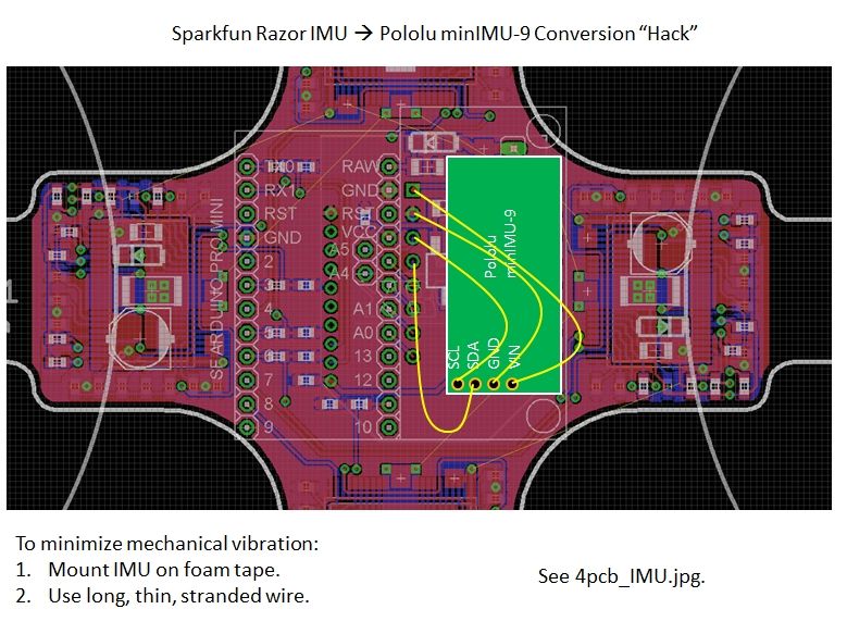
4pcb_IMU.jpg – Image showing vibration mounting and wiring of Pololu minIMU-9.
4pcb_SCH.pdf – PDF schematic of the board.
Bill of Materials / Cost:
The Bill of Materials (4pcb_BOM.xlsx) lists all the components required to put together one PCB quadrotor and ground station. The total cost to build the quadrotor is about $240. The ground station consists of a USB game controller, an XBee radio, and and XBee-to-USB adapter. If you don’t already have these, they add an additional $80 or so.
Soldering:
This board requires a good amount of surface-mount soldering, including passives as small as 0603 and four TSOP36 ICs. They can all be hand-soldered (no BGA or leadless).
Additional Tools and Hardware:
– Wire (22AWG and 28AWG stranded would work) and wire cutters/strippers.
– Solder braid for cleaning up bridges.
– FTDI cable for programming the Arduino Pro Mini.
– Hex key set.
– Double-sided foam mounting tape.
Software:
-EAGLE
If you want to modify the printed circuit board, you’ll need EAGLE v6.0.0 or later. You can download it here. The free “Light Edition” is sufficient, even though the outline of the board is larger than 100x80mm limit (see Step 2). You will also need EAGLE to reference the board layout when placing components. (e.g. Type “show R32” in the board window command line to figure out where to put resistor R32.) There are no designators on the board itself.
-Arduino
The flight controller is written in the Arduino IDE. You can download the latest version from here. Make sure you set the board type to “Arduino Pro Mini (5V/16MHz) w/ ATmega328”.
-Visual Basic Express (Optional)
The ground station is programmed in Visual Basic Express. If you want to modify the ground station software, you can download the free edition, Visual Basic Express 2010 from here.
-.NET Framework
The ground station requires the .NET Framework runtime files. (Unfortunately, this makes it Windows-only.) These files come with Visual Basic 2010, so if you plan on modifying the ground station software, there’s no need to download them separately. If you just want to run the ground station executable, you can download the .NET Framework runtime files from here.
-Processing? (Optional)
Although I haven’t done so myself, it is possible to port the ground station software over to Processing, which would make it compatible with other operating systems. To read from the USB game controller, there is a third-party library called ProCONTROLL. I did some work with this for a XBee-based robot controller, the details of which are here. This could be a good starting point for making a non-Windows ground station.
 4pcb_DOC.zip1 MB
Step 2: Board Design
4pcb’s Printed Circuit Board is its main structural component and electronics motherboard. The second most time-consuming part of the project was probably designing the board in EAGLE. (The most time consuming part is programming the flight controller and tweaking the controls.) I included the Gerber files required to manufacture an exact copy of 4pcb’s PCB in the project documentation files (Step 1). In that case, you can skip to the next Step, which talks about board manufacturing options. But, I strongly encourage anyone who is interested in modifying the board design to pop open the EAGLE files and go for it!
How to Cheat EAGLE Light’s Board Size Limit (A Little):
4pcb is quite a bit larger than the 100x80mm board size limit for the free EAGLE Light Edition. One reason I put off starting this project was because I didn’t want to pay for the full version or switch to a different board layout software. But then I discovered something interesting: The board size limit applies only the placement of components. You can route traces, add holes, and create a board outline that extend far outside the 100x80mm box.
4pcb’s centroid is right at the middle of the 100x80mm bounding box. All the components fit in the center part of the board, inside this restricted area. The arms, including the motor mounting holes, stretch out in all directions including going into negative coordinates. This is fine – the Gerber files still seem to render properly.
Board Outline:
4pcb’s board outline (“Dimension” layer in EAGLE) is actually the shape of the quadrotor frame. Most board printing companies will route the outside dimension of your board to any shape you specify. (Make sure this is an option before you order.) Drawing the shape took some practice using the arc tools in EAGLE. One idea that’s been suggested is to add diagonal supports between the arms. However, this would create areas of internal routing, and most board companies charge extra for that.
Rotational Symmetry and Copy-Paste:
The four motor controller blocks are rotationally symmetric. I routed this board in EAGLE 5.11, when Copy-Paste of component groups was more difficult. I think it’s much more straightforward in EAGLE 6.0.0 and later. But it definitely still saved a lot of routing time to be able to make four identical copies of the motor controller block. If you’re using an older version of EAGLE (prior to 6.0.0), the rough process for Copy-Paste is as follows:
1. Create and route the component block to be copied. Do this first, before any non-copied components are placed or routed. This will help auto-numbering not break.
2. Close the schematic. This breaks the back-annotation check so that you can Copy-Paste on the board itself.
3. Select the group and perform a group copy (Ctrl + Right Click). Paste, move, and rotate as desired.
4. Re-open the schematic. Ignore all the errors. Copy-paste the schematic group containing exactly the same components and nets as the board group.
5. The auto-numbering should work, but if it doesn’t you may have to clean up some designators manually to make them match the board copy.
6. Repeat.
The process should be much simpler in EAGLE 6.0 or later, and shouldn’t require breaking the back-annotation. I haven’t gotten around to trying it yet, though.
Step 3: Board Printing
Make it real.
Below is a list of just a few board printing companies. They should all take the standard set of Gerber files. For a two layer board, there should be up to seven files. The Gerber files for 4pcb are included in the project documentation files (Step 1).
Layer Definitions:
Top Silkscreen (pcbqr.GTO)
Top Solder Mask (pcbqr.GTS)
Top Copper (pcbqr.GTL)
——————————————
NC Drill (pcbqr.TXT)
——————————————
Bottom Copper (pcbqr.GBL)
Bottom Solder Mask (pcbqr.GBS)
Bottom Silkscreen (pcbqr.GBO)
You can probably live without the silkscreen, since the component density is too high for designators to be useful anyway. (You’ll have to reference the EAGLE files to place all the parts.) The soldermask is absolutely necessary for this board, though. A bare board will be too difficult to solder.
Board Printing Services:
-Advanced Circuits (www.4pcb.com)
Fast and reliable (US-based), but expensive shipping. If you are a student, use the 33each discount to get a single board for $33 + shipping. This is where I got mine printed. And yes, the name “4pcb” comes from this site’s URL, though they are not an official project sponsor or anything.
-MyRO PCB (www.myropcb.com)
Inexpensive and usually fast.
-Dorkbot PDX (www.dorkbotpdx.org/wiki/pcb_order > now www.oshpark.com?)
Group order, so it could be slower, but good pricing.
There are many others. Shop around. Just make sure that external routing to non-rectangular shapes and soldermask on both sides are standard options.
Step 4: Solder Lots of Tiny Parts
Depending on your mood, this step can either be very relaxing or very boring. Definitely find a nice soldering station to work at (or if you are more into hot-plate or reflow soldering, go for that). It took me two sittings to solder everything.
Locating Components:
The part designators (e.g. “R15”) on the “Names” layer in EAGLE are not rendered on the silkscreen. I chose to leave them off because the component density is high enough that making them not overlap would be a time consuming process. Instead, the method I usually use for placing parts is to have the EAGLE board open on a nearby computer and using the “show” command to highlight each component as I go. (See the third image for an example of this.)
Step 5: External Wiring
I failed in my goal of completely containing the quadrotor circuit to a single PCB with no external wiring. There are two sets of external wires to connect, 12 wires in total, each with good reason. The external wiring is summarized in 4pcb_EXT.pdf in the project documentation (Step 1).
Pololu minIMU-9 Mounting and Wiring:
This quadrotor’s original design called for the now-obselete Sparkfun 6DOF Razor IMU. The new design uses the Pololu minIMU-9. The minIMU-9 is a digital IMU, which has some nice benefits (higher resolution ADC than the Arduino, self-zeroing). It’s also smaller than the Razor IMU was and only requires four connections to communicate with the Arduino Pro Mini over I2C serial.
I didn’t modify the board to have a minIMU footprint because I found that the IMU has to be mounted on foam tape anyway in order to minimize the effects of mechanical vibration transmitted through the frame. (The vibration really messes with the gyros, in ways that can’t even be filtered out.) I found that making a loop of foam tape works even better than one or two layers alone. Also, I found that adding mass to the IMU, by taping small pieces of aluminum to the bottom, helped. (See the third image.)
After mounting the IMU to the frame, the four connections should be made with thin, flexible external wires (also to minimize vibration). Conveniently, the connectors can go right to the first four pins of the now-unused Sparkfun IMU header. (See first image.)
External Power Wiring:
The power wiring carries high current, so I thought it would be a good idea to keep it off-board. In retrospect, I wish I had put the external power wiring on the board. This is something I would definitely modify in v2. There is enough room to route a few large traces around to carry power and ground to the four motor controllers, especially with the Sparkfun IMU headers out of the way.
For now, though, the power wiring is done externally with 22AWG or larger, preferably stranded wire. There are a total of 8 wire jumps to make, four for power and four for ground. (See the second image.) To eliminate ground loops, a star configuration from the battery power input to each motor controller could be used. I found that a bus works okay, though. (Keep in mind that in a bus, the wires feeding out from the main power input carry the most current.) Be very careful not to reverse any of these connections, or it will instantly destroy the motor controller on power-up.
Step 6: Motors!
This PCB quad uses four tiny brushless motors for propulsion. They’re the HXM1400-2000 “hexTronik 5gram Brushless Outrunner 2000kv”. They’re designed for 2S (7.4V) batteries, and the quad will fly with a 2S battery. However, the minimum voltage rating of the Toshiba TB6588FG driver chip is 7V, which is cutting it a little close for 2S. I found that a 3S (11.1V) battery, even one that it slightly heavier than the 2S, increased flight time and didn’t cause the motors to overheat.
The 10g version and 20g version of this motor fit the same mounting pattern and can swing a much larger propeller, so it might be possible to make a larger version just by extending the arms. Stiffness would be a concern at that point. The 2g version might also fit the same mount, for an even smaller quad, but its rpm/V is too high to run effectively on 3S and it’s speed might exceed the RPM limit of the Toshiba TB6588FG.
Mounting:
The motors bolt directly to the PCB with short 2-56 machine screws. The wires should be facing inward and the hole directly under the wires may be inaccessible. That’s okay: three screws will do. The two side screws should get 2-56 nuts. The outermost screw will be used to attach the landing gear in the next Step, so it doesn’t need a nut. Use threadlocker (Loctite) on all the screws otherwise vibrations will cause them to loosen.
Wiring:
The motor wires are pre-tinned and can be soldered directly to the three output pads of the motor controller component block, which are on the bottom layer of the board. Sometimes, the wires come long enough to reach around the arms. Other times, they are too short. You can either make wire extensions or drill a hole in the arm for a more direct line to the pads. (See the third image.)
Step 7: Landing Gear and Motor Shock Proofing
Building a quad means lots of crash landings.
Small quadrotors are nice because they can survive crashes pretty well. There are a few weak links, though, and this step tries to address those.
Landing Gear:
The landing gear I chose were 1″-long aluminum 2-56 standoffs. I originally tried plastic ones, but they broke off on tough landings. The aluminum ones are much more durable, for not very much weight penalty. They attach directly to the outermost motor mounting screw (use threadlocker). To cushion the landings, I added four small silicone feet to the landing gear. Without these, the shock from the landings is transmitted directly into the motor, which can sometimes case its rotor press fit to fail (see below).
Shock-Proofing the Motors:
By far the most common failure mode I found during crash landings was the motor cans coming apart. (See the second image.) The shock from a crash would cause the narrow interference fit to fail, and no amount of superglue or Loctite would keep it together. The problem with adhesives like that is that the joint is brittle, so the shock just cracks the adhesive off.
I found a much better solution was to actually heat shrink the entire motor. You can see this in the first image: three of the four motors are heat-shrinked. This probably reduces motor cooling a bit, but the compliant heat shrink does a much better job of holding the rotor together under the shock loads of a crash landing. Just be careful to cut and shrink the tubing evenly, or it will throw off the balance of the rotor a lot.
- What is the primary structural component of the 4pcb?
The Printed Circuit Board acts as both the main structural frame and the electronics motherboard. - How does the 4pcb handle motor control without external ESCs?
It uses integrated Toshiba TB6588FG driver chips on the PCB to control the brushless motors directly. - Can I use the free EAGLE Light Edition to design this board?
Yes, by placing all components within the 100x80mm limit while allowing the board outline and traces to extend beyond it. - Why is foam tape used for the IMU mounting?
It minimizes mechanical vibrations transmitted through the frame which would otherwise disrupt the gyro readings. - What battery voltage is recommended for optimal flight time?
A 3S (11.1V) battery is recommended over a 2S battery to increase flight time and prevent motor overheating. - How can you prevent motor cans from separating during crashes?
Heating shrink tubing around the entire motor provides a compliant seal that holds the rotor together under shock loads. - What type of wire should be used for external power connections?
Use 22AWG or larger stranded wire to safely carry the high current required by the motors. - Does the ground station software run on non-Windows operating systems?
The provided executable requires Windows due to .NET Framework dependencies, though porting to Processing is possible. - What is the estimated total cost to build the quadrotor?
The total cost to build the quadrotor is approximately $240. - How long does the 4pcb fly with a full charge?
The flight time is approximately 8 minutes when weighing 138 grams.