Summary of SD Card Data Readable Anywhere
This article describes a portable handheld device designed to browse book and movie collections stored on an SD card. Using an ATMega328 microcontroller, a 20x4 LCD display, and five switches, the project allows users to scroll through text files organized by author or title while away from home. The system runs on a 9V battery and features a custom menu for selecting file types or adjusting settings, eliminating the need to rely on memory during shopping trips.
Parts used in the Portable Collection Scanner:
- PCB (2x3 size)
- ATMega328
- Momentary SPST PB Switches
- On/Off SPDT Switch
- SD Card Reader
- Standard Regulator 5V
- 9V Battery Clip
- Green LED
- LCD Display (20x4)
- Electrolytic Capacitors
- Capacitors
- Crystal
- Low Forward Resistance Diodes
- Resistors
- Enclosure
- 9V Battery Holder
- 9V Battery
- SD Memory Card
- Minimalist Arduino Circuit Kit
- ZIF Socket
- IDE Cable
This project started as many of mine usually do, as a honey-do. We have compiled an extensive list of our book and movie collections on our computer at home, but my wife wanted to be able to scan the list from the video store (yes, we still go to the video store).
So I created a hand held device that allows us to scroll through text files stored on an SD card. I have my video collection and science fiction book collection organized by title and saved to this card. Not having to rely on my own fading memory about what we’ve already read or seen, now we can reference our entire collection while we are in the book or video store.
The solution I came up with was to use a 20×4 LCD display and an SD card to hold the text files and display each record in four lines on the LCD. I programmed an ATMega328 to read a text line from the SD card and display it on the LCD. It’s all wired to a small circuit board.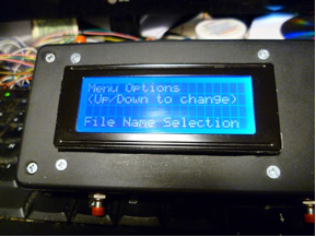
I kept the text files small by dividing the contents by author for the books and by title for movies (authors starting with the letter A will be located in the text file Books-A.txt).
The device has five switches: power, reset, menu, up and down, LCD display and SD card reader. When the menu button is pressed, the main menu is displayed. This allows us to choose File-Selector, Delay Change, Credits, Read Book List, or Read Movie List.
The ATMega328 and other components are placed on a PCB (Mega is socketed), according to schematic below. The LCD is connected to the PCB via IDE cable. The SD card is soldered right to the PCB in a position that allows the opening to be access through the box. Finally, the SD board is connected to the ATMega via shorting wires.
I wrote the code for the Arduino but it does use the tinyFAT code that was written by someone else and then included in the Arduino library as of version 022.
Part List
| Part Description | Mfr. Part No. | |
| PCB (2×3 should be big enough) | 21-225 | |
| ATMega328 | ATMEGA328P-PU | |
| Momentary SPST PB Switches | GPB001-R | |
| On/Off SPDT Switch | TPC11FGRA2 | |
| SD Card Reader | U10-00062 | |
| Standard Regulator 5V | LM7805 | |
| 9V Battery Clip | A104-R | |
| Green LED | LTL-307G | |
| LCD Display (I used 20×4) | NHD-0420DZ-FLYBW | |
| 10µF Electrolytic Capacitors | R10/50 | |
| 22pF Capacitors | DC22 | |
| 16MHz Crystal | CY16 | |
| Low Forward Resistance Diodes | HSMS-2860-BLKG | |
| 10K Resistors | CF1/4W103JRC | |
| 1K Resistor | CF1/4W102JRC | |
| 220Ω Resistors | CF1/4W221JRC | |
| Enclosure (dictated by size of LCD – I used 5×2.75×1.5) | H2853-R | |
| 9V Battery Holder (metal ‘U’ clip fits best) | GBH-1009-R | |
| ALK 9V 522 | 9V Battery | |
| SD Memory Card (2GB) | ||
| Minimalist Arduino Circuit Kit | BB-ARDUINO | |
| ZIF Socket | 28-52610 | |
| IDE Cable (cable dictated by LCD pin count) | 2102-218 |
Note: The ATMega328 was programmed via Jameco’s Minimalist Arduino Circuit Kit with one change. The socket in the kit was replaced with a ZIF so that ICs programmed on the breadboard can easily be removed and placed into a socket on a PCB.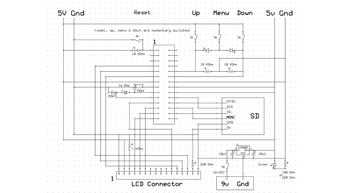
Project Notes:
| •
• • |
Almost any method may be used to connect the LCD to the PCB. I used an old IDE cable so that I could remove the lid entirely while I worked on soldering up the switches.
The forward resistance of the diodes will affect the ON state of A0 and A1. If the MENU button is not being registered correctly when pressed, you might have to change the value in the sketch of ButtonOnValue (lowering this value will mean you could use diodes that have a higher forward resistance value). Just be careful not to lower this too much because you don’t want ghosting. |
For more detail: SD Card Data Readable Anywhere
- How does the device store collection data?
The device stores text files on an SD card, dividing contents by author for books and by title for movies. - What components are used to display information?
A 20x4 LCD display is used to show each record in four lines. - Can I change the delay between records?
Yes, the main menu includes an option called Delay Change to adjust this setting. - Does the ATMega328 use a permanent socket?
No, the ATMega328 is placed in a ZIF socket so it can be easily removed and replaced. - How are the buttons connected to the microcontroller?
The device uses five switches including power, reset, menu, up, and down, connected via shorting wires. - What happens if the MENU button fails to register?
You may need to lower the ButtonOnValue in the sketch if diode forward resistance affects the ON state of A0 and A1. - Is the code written from scratch?
The code was written for Arduino but utilizes tinyFAT code included in the Arduino library version 022. - How is the LCD connected to the PCB?
The LCD is connected via an IDE cable, which allows the lid to be removed easily during assembly.