Summary of Arduino MIDI-in shield
This project demonstrates how to build a MIDI input shield for Arduino, allowing connection to MIDI devices like master keyboards. The design centers on an optocoupler circuit with resistors to electrically isolate the Arduino from the MIDI device. The shield uses a 5-pin DIN MIDI connector and can work with various optocouplers such as the 4N28 or 4N35. The tutorial includes schematic files, PCB layouts for etching, and practical tips for board production and soldering.
Parts used in the Arduino MIDI-in shield:
- 220 Ohms resistor
- 100 kOhms resistor
- 3.3 kOhms resistor
- 1N4148 diode
- 4N28 optocoupler (or 4N29, 4N35 as alternatives)
- 5 PIN DIN MIDI connector
- 2x 1x8 pinheads
- 1x 1x4 pinhead
- 1x 1x6 pinhead
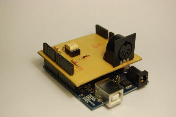
This instructable shows how to build a shield to connect devices that send MIDI signals (e.g. a masterkeyboard) to an Arduino.
The basic schematic is derived from: http://www.arduino.cc/cgi-bin/yabb2/YaBB.pl?num=1187962258/
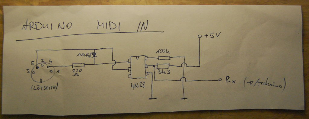
Step 1: The schematic
Basically the schematic is just an optocoupler with some resistors to decouple the MIDI device from the Arduino.
Note that the DIN connector on the left side is seen from the back (solder pin-side).
Step 2: Board layout, parts list, etc.
Diode: 1N4148
Optocoupler: 4N28
5 PIN DIN connector (MIDI connector)
2 pinheads 1×8
1 pinhead 1×4
1 pinhead 1×6
 It will also work with other Optocouplers (e.g. a 4N35, I used a 4N29)
Attached are the necessary files for etching the board and the eagle-files if you want to make modifications.
Step 3: Production
Just a few hints for making the shield:
A very good how-to (that actually worked form me unlike many others) for etching the board can be found here: http://hackaday.com/2008/07/28/how-to-etch-a-single-sided-pcb/
If you are a noob like me and want to modify the board in eagle then try these instructables:
http://www.instructables.com/id/Draw-Electronic-Schematics-with-CadSoft-EAGLE
http://www.instructables.com/id/Turn-your-EAGLE-schematic-into-a-PCB
http://www.instructables.com/id/Make-hobbyist-PCBs-with-professional-CAD-tools-by-
Soldering the pinheads upwards down on the board so you can directly put it on the arduino is a real pain in the ass. I rasped a head of my soldering iron so that it became small enough to do that job. let me know if you have a better solution.
For this board I used a DIN connector that can be soldered directly to it. If you want to use another one be sure to connect the pins with the numbers on the board to the according pins on the connector. In the pic here the pins are seen from the back (where you solder).
Resistors
Diode: 1N4148
Optocoupler
For more detail: Arduino MIDI-in shield