Summary of Arduino MIDI Chiptune Synthesizer
This article details a DIY 8-bit chiptune synthesizer project using an Arduino and an AY-3-8910 (or YM2149F) sound chip. It functions as a USB MIDI device compatible with modern DAW software, recreating authentic 1980s sounds without specialized editing software. The build costs approximately £20 and requires basic soldering skills to assemble on a prototyping board.
Parts used in the 8-Bit Chiptune Synthesizer:
- Sparkfun Pro Micro clone (5V, 16MHz option)
- Yamaha YM2149F PSG chip
- Two 100nF ceramic capacitors
- One 75R resistor
- One 1K resistor
- One 100K resistor
- One 4.7nF ceramic disc capacitor
- One 1uF electrolytic capacitor
- 40-pin 0.6" DIP IC socket
- Two 12-way 0.1" headers
- Prototyping board (3" by 2")
- PCB mount phono socket
- Miniature solid-core wire
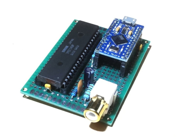
Relive the fun of early computer game music with an authentic 8-bit chiptune synthesizer, which you can control over MIDI from the comfort of any modern DAW software.
This simple circuit uses an Arduino to drive an AY-3-8910 programmable sound generator chip (or one of its many clones) to recreate that 1980’s sound. Unlike the many designs that need specialised software to edit music, this looks like a standard USB MIDI device. The synthesizer has a clever algorithm which tries to keep the most musically-relevant notes playing; in many cases you can throw un-edited MIDI files straight at it and the tune comes right out. Total cost should be about £20.
Step 1: Things You’ll Need
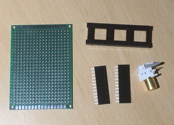
The full parts list for this, as you see in the pictures, is as follows:
- Sparkfun Pro Micro clone (5V, 16MHz option). I used this one on Amazon.
- Yamaha YM2149F PSG chip. I got mine from eBay.
- 2 x 100nF ceramic capacitors
- 1 each of 75R, 1K and 100K resistors (1/4 watt rating is fine).
- 4.7nF ceramic disc capacitor
- 1uF electrolytic capacitor (voltage rating > 5V).
- 40 pin 0.6″ DIP IC socket
- 2 x 12 way 0.1″ headers (this one from CPC)
- Prototyping board, 3″ by 2″ approx. I bought a bulk pack of these, again on Amazon.
- PCB mount phono socket
- Miniature solid-core wire (like this).
You will also need a soldering iron, solder, wire cutters, pliers, and a wire stripper.
Step 2: Alternative Parts
Alternative programmable sound generator chips
The YM2149 I used is a clone of the original General Instruments AY-3-8910 IC. (The first prototype used an AY-3-8910 I bought from eBay, but it turned out the white noise generator wasn’t working. Sad face). You can use either for this project without any changes.
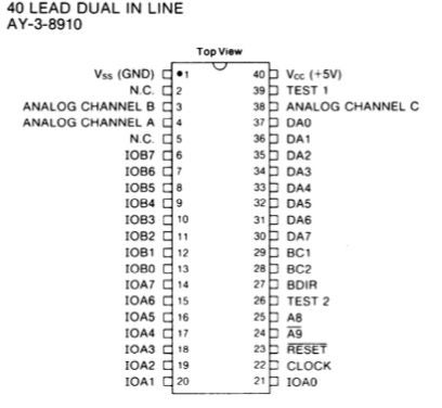
General Instruments also made AY-3-8912 and AY-3-8913 variants, which was the same silicon inside smaller packages, without some extra I/O pins. These pins aren’t needed for any audio purposes, and this project doesn’t use them. You can use an AY-3-8912 or -8913, just follow the pinouts shown above.
Alternative Arduinos
The “Pro Micro” I used is a copy of Sparkfun’s Pro Micro board. If you’re not confident with Arduino code it’s best to stick with this; if you’re happy to adapt the design, you’ll need the following specifications
- ATmega 16u4 or 32u4 device (needed to act as a USB MIDI device; the ATmega 168 or 328 can’t do this).
- 5V operation (the AY-3-8910 runs at 5V), and 16MHz clock speed.
- At least 13 digital I/O lines.
- Port pin PB5 must be connected (it’s used to generate a 1MHz clock signal). On the Pro Micro this is used as the D9 I/O pin.
The Arduino Leonardo and Micro boards both fit the bill, although I haven’t tried them.
Other components
The resistors and capacitors used here aren’t particularly special. Any parts of (approximately) the right value should work.
Step 3: Laying Out the Circuit Board
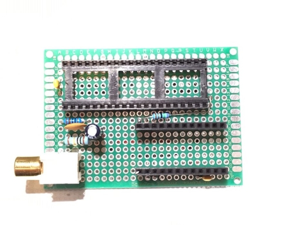
To build the circuit, it’s best to start by positioning the sockets, then add the resistors and capacitors. We’ll cover wiring these together in the next step.
Using the picture above as a guide, position the 40-pin IC socket, turn the board over and just solder in two opposite corner pins first. If the socket isn’t then lying flat against the board, it’s easy to fix by resoldering one or other pin. When it’s OK, solder the rest.
Position the two 12-pin sockets, then insert the Arduino into them to hold them vertical and steady during soldering. Again, soldering two pins at each end first will allow a check before final soldering.
For the audio output socket, I used a small drill to enlarge the PCB holes, as the mounting tags are rather large.
Read more: Arduino MIDI Chiptune Synthesizer
- How does this synthesizer connect to modern software?
The circuit acts as a standard USB MIDI device that can be controlled from any modern DAW software. - Can I use unedited MIDI files with this project?
Yes, a clever algorithm allows you to throw un-edited MIDI files at it to play the tune directly. - What is the estimated total cost for this project?
The total cost should be about £20. - Which alternative sound chips are compatible with this design?
You can use the General Instruments AY-3-8910, AY-3-8912, or AY-3-8913 variants. - Does the ATmega 168 or 328 microcontroller work for this project?
No, these cannot act as a USB MIDI device; you need an ATmega 16u4 or 32u4 device. - Can I use an Arduino Leonardo instead of the Pro Micro?
Yes, the Arduino Leonardo fits the bill, though the author has not personally tried them. - What voltage must the power supply provide for the sound chip?
The system requires 5V operation because the AY-3-8910 runs at 5V. - Is a special clock speed required for the microcontroller?
Yes, the project requires a 16MHz clock speed.