
Summary of Arduino Masterclass Part 2: Build an LED weather station using arduino
This article outlines Part 2 of an Arduino masterclass focused on building a weather station that measures temperature and humidity. It introduces seven-segment displays and multiplexing techniques to control two displays using limited Arduino pins. The project utilizes transistors as switches to manage the display segments efficiently, alongside standard breadboard components and a DHT11 sensor for environmental data collection.
Parts used in the LED Weather Station:
- Arduino board
- Breadboard
- Wires
- Pliers
- DHT11 temperature/humidity sensor
- 7 x 330-ohm/0.5W metal film resistors
- 3 x 4.7k-ohm/0.5W metal film resistors
- 2 x BC337 NPN transistors
- 2 x LTS543R or FND500 common cathode seven-segment displays
Project-specific parts
You’ll need the standard parts (Arduino board breadboard wires pliers and so on) along with these extras:
- DHT11 temperature/humidity sensor
- 7 x 330-ohm/0.5W metal film resistors
- 3 x 4.7k-ohm/0.5W metal film resistors
- 2 x BC337 NPN transistors
- 2 x LTS543R or FND500 common cathode seven-segment displays
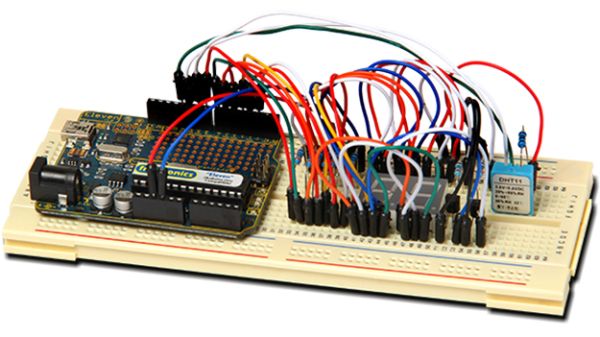
They shouldn’t cost you more than $15 all up and you can get everything bar the DHT11 from Jaycar Electronics.
In Part 2 of our Arduino masterclass we’re cracking on to build a weather station that measures temperature in degrees Celsius and relative humidity as a percentage. We’ll introduce new components and theory and put the lot into practice.
Seven-segment displays
LEDs on their own are great indicators but to display quantitative information we need something more and that’s where seven-segment displays come in. These are blocks with seven LEDs arranged into a figure eight each individually controllable. As we described last previously LEDs have two connections: an anode (A) and a cathode (K). When current flows from anode to cathode the LED lights up. However to reduce the display pin count from 14 to 10 most displays have either all of their anodes or cathodes joined together to a single pin – they’re known as common anode or common cathode displays.
We’ll be using the LTS543R common cathode type – they’re a garden variety display and the most complicated part of using them is knowing the pin layout. Here’s how you do it: hold the display in front of you with the decimal point LED at the bottom-right. The bottom-left pin at the back is pin 1 counting right to pin 5 and the top-right pin is pin 6 counting left to pin 10.
Driving seven-segment displays
To drive a seven-segment display you need seven data lines from an Arduino to control the seven LEDs. If you add a second display you’ll need another seven data lines. A third is another seven. So you can see the control pin count can skyrocket if we keep using this system.
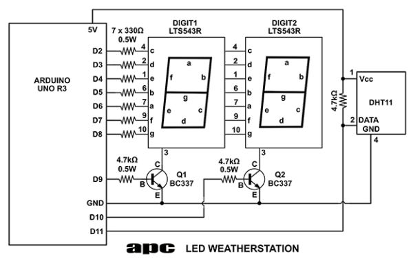
Our weather station uses two displays and while the Arduino Uno R3 has 14 outputs to play with we’re going to do it with just nine using a technique known as multiplexing. Put simply it’s a way of being able to send data to different devices over the one set of control lines (data bus) using a time-share system. A simple analogy is driving your car: you (probably) don’t have your own dedicated roads you use the same roads as everyone else. If you think of it in the time domain you’re time-sharing a road for the time you’re on it. What we’re doing is similar – we’re multiplexing 14 LEDs’ worth of data over a seven-bit data bus using a similar time-share method.
Multiplexing
We’re going to need another two control lines to make it work. This is also a good time to introduce you to another new component: the transistor. Your average Ivy Bridge-class Core i5 processor has 1.4 billion of these things and we need just two. Transistors are clever little devices that can amplify a signal and act like controllable switches. In every case a transistor lets you control a larger current with a smaller one. If you follow the circuit diagram we’re using them as switches connected to the common cathode pin of each display.
The transistor in our circuit is a BC337 NPN medium-signal transistor. It’s a garden variety three-pin device and here’s how to tell the pins: hold the transistor flat-face facing you with the pins pointing down. The pin on the left is known as the collector (C) the pin on the right is the emitter (E) and the one in the middle is the base (B). You could write two books on transistor theory but for now that’ll do.
For more detail: Arduino Masterclass Part 2: Build an LED weather station
- What does the weather station measure?
The station measures temperature in degrees Celsius and relative humidity as a percentage. - How many seven-segment displays are used in this project?
The project uses two seven-segment displays. - Why is multiplexing necessary for this build?
Multiplexing allows the system to drive fourteen LEDs using only nine control lines instead of fourteen separate data lines. - Which transistor model is recommended for this circuit?
The project specifies using the BC337 NPN medium-signal transistor. - How do you identify the pins on the LTS543R display?
Hold the display with the decimal point at the bottom-right; the bottom-left back pin is pin 1 counting right to pin 5, and the top-right pin is pin 6 counting left to pin 10. - Can you get all parts from Jaycar Electronics?
You can get everything except the DHT11 sensor from Jaycar Electronics. - What is the estimated cost for the extra parts?
The extra parts should not cost more than $15 all up. - How do transistors function in this specific circuit?
The transistors act as controllable switches connected to the common cathode pin of each display to control larger currents with smaller ones. - What is the total number of control lines needed when adding a second display without multiplexing?
Without multiplexing, adding a second display would require another seven data lines, increasing the count significantly. - What type of LED connection configuration do common displays use?
Most displays join all anodes or all cathodes together to a single pin to reduce the display pin count from 14 to 10.
