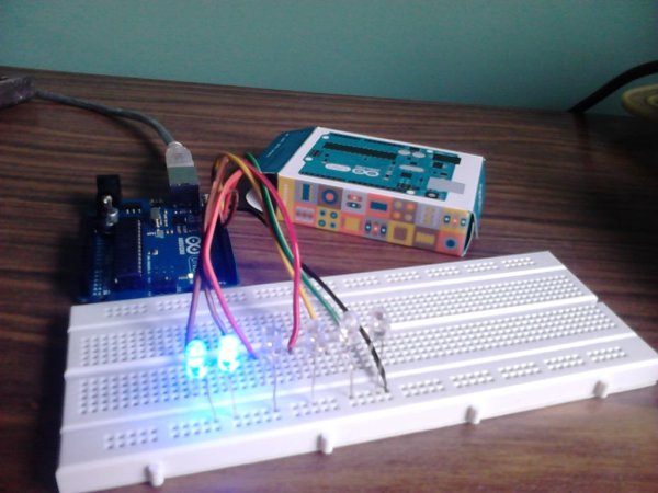
Summary of Arduino led pendulum
This article details the wiring and coding process for an Arduino LED pendulum project. It covers stripping wires, connecting them to specific Arduino pins (8–13) and a breadboard, attaching six LEDs with correct polarity, and uploading a C++ sketch to control the lights. The guide emphasizes using an Arduino Uno, jumper wires, LEDs, and basic tools like wire strippers.
Parts used in the Arduino LED Pendulum:
- Arduino board (Arduino Uno preferable)
- USB A to B cable
- Breadboard
- 7 pieces of wires (preferably differently coloured and more than 6 inches in length)
- 6 LEDs (any color)
- Wire stripper and cutter or pliers
Step 2: Putting up the wires
Strip both ends of wires
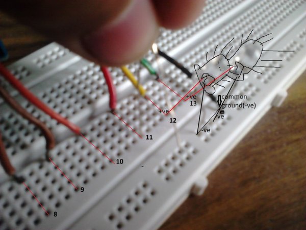
-insert one end of each wire into sockets numbered
-Gnd(black wire in my case)-this will be the common ground connection
– 13 (green wire in my case)
– 12 (yellow wire in my case)
– ~11 (orange wire in my case)
– ~10 (red wire in my case)
– 9 (brown wire in my case)
– 8 (brown wire in my case)
Step 3: Hooking up wires to the breadboard
– hook up the wire connected to gnd(black in my case) to the common vertical line on the the sides of the breadboard
– connect other wires to different horizontal lines at at-least 3 lines left in between(just for convenience)
Confused?-see image
Step 4: Hook up the LED
– Put up the shorter end(-ve) of each led to the common ground line on the vertical line
– put up the longer end(+ve) of each led to the respective coloured wire connected horizontal line
Step 5: Write, compile and run the sketch
open the arduino software
copy and paste the following sketch-

int led1 = 13;
int led2 = 12;
int led3 = 11;
int led4 = 10;
int led5 = 9;
int led6 = 8;

// the setup routine runs once when you press reset:
void setup() {
// initialize the digital pins as outputs.
pinMode(led1, OUTPUT);
pinMode(led2, OUTPUT);
pinMode(led3, OUTPUT);
pinMode(led4, OUTPUT);
pinMode(led5, OUTPUT);
pinMode(led6, OUTPUT);

}
Getting the parts
parts needed-
– An arduino board(arduino uno preferable for starters)-don’t worry if u have other and a to b cable
get it here(for Indians)- http://shop.sumeetinstruments.com/index.php?route=product/product&path=69_70&product_id=374
– A breadboard
– 7 pieces of wires(preferably differently coloured and more than 6 inches in length)- jumper/solid core preferable
– 6 leds (any color)
tools needed-
– wire stripper and cutter/or pliers (you don’t need them if you have a pair of strong jaws like me) 🙂
For more detail: Arduino led pendulum
- Which Arduino pins are used for the LED connections?
The project uses digital pins 8, 9, 10, 11, 12, and 13. - How should the LED legs be connected to the ground line?
The shorter negative (-ve) end of each LED must be put up to the common ground line on the vertical line. - What is the recommended type of wire for this project?
Jumper or solid core wires that are preferably differently coloured and more than 6 inches in length are recommended. - Can I use a different Arduino board if I do not have an Uno?
Yes, you can use other boards if you have an A to B cable. - What tool is needed if you do not have strong jaws for cutting wires?
You need a wire stripper and cutter or pliers. - How many horizontal lines should separate the wires on the breadboard?
Wires should be connected to different horizontal lines at least 3 lines left in between for convenience. - What software is required to run the sketch?
The Arduino software is required to open, compile, and run the code. - What does the setup routine initialize in the code?
The setup routine initializes the digital pins as outputs.