Summary of Arduino LED Flasher Circuit
This article explains how to build a simple Arduino LED flasher circuit. Using an Arduino board, an LED, and a USB cable, the project connects the LED to digital pin 13 and ground. The system is powered via USB from a computer and programmed using Processing language code to toggle the LED on and off in one-second intervals repeatedly.
Parts used in the Arduino LED Flasher:
- Arduino Board
- LED
- USB Connector
In this project, we will go over how to build an arduino LED flasher circuit.
We will use a standard arduino board, doesn’t matter which, and connect it so that it flashes an LED a certain amounts of times on and off repeatedly to create an LED flasher circuit.
An arduino is a self-contained microcontroller. Therefore, it can be programmed via the language Processing to turn the LED on for a certain period of time and turn it off for a certain period of time- over and over. To control the amount of time the LED will be on and the amount of time it will be off can easily be decided by our software code.
Once the arduino board is connected to a computer via USB, it has 5V of power. It gets power via the USB. The LED is then connected to its digital output pin. All we must then do is write our program which flashes the LED on and off.
Components Needed
- Arduino Board
- LED
- USB Connector
The arduino board can be any of several. It can be an arduino uno, duemilanove, etc.
The 5 volts of power, again, comes from the USB connection from the arduino board to the computer.
The USB connector that needs to be used is one which has a USB type A connector on one side and a Type B connector on the other.
Arduino LED Flasher Circuit
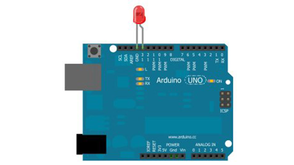
To build this circuit, we simply connect the anode of the LED (the longer of the 2 ends) to digital pin 13 of the arduino board and the cathode of the LED to the ground Pin of the arduino board.
The circuit connected will look like this:
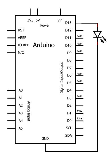
The schematic diagram for this circuit is:
Once the circuit is connected in this way, all we have to do is take the USB connector and plug the type A connector into the computer and the type B connector into the arduino board.
The USB type A connector goes into the computer which will program the arduino and the USB type B connector goes into the arduino board. Now the arduino has direct connection to the computer and can be programmed. Arduinos are programmed via USB connections.
The last stage now is to write and then run the code which will make the LED connected to the board flash on and off.
Arduino LED Flasher Code
The code needed to flash the LED on the arduino board is shown below.
It is written in the processing language and ran through USB connection.
//Flashing LED Circuit

const int LED= 13;//LED connected to digital pin 13

void setup()
{
pinMode(LED, OUTPUT);  //sets the digital pin as output
}

void loop()
{
digitalWrite(LED,HIGH);  //turns the LED on
delay(1000);  //waits for a second
digitalWrite(LED,LOW);  //turns the LED off
delay(1000);  //waits for a second
}
For more detail: Arduino LED Flasher Circuit
- What power source does the Arduino board use?
The Arduino board receives 5 volts of power directly from the USB connection to a computer. - Which pins should the LED be connected to?
The LED anode connects to digital pin 13, and the cathode connects to the ground pin. - How can the flashing speed be changed?
The duration the LED stays on and off is controlled by adjusting the software code delays. - Can any type of Arduino board be used?
Yes, any standard Arduino board such as an Uno or Duemilanove can be used for this project. - What type of USB connector is required?
A USB connector with a Type A end for the computer and a Type B end for the Arduino is needed. - In what programming language is the code written?
The code is written in the Processing language and executed through the USB connection. - How does the loop function control the LED?
The loop sets the pin to HIGH to turn the LED on, waits one second, sets it to LOW to turn it off, and waits another second. - What happens when the USB Type A connector is plugged into the computer?
Plugging the Type A connector into the computer allows the Arduino to be programmed and receive power.