Summary of Arduino ISP (In System Programming) and stand-alone circuits
This article details how to use an Arduino Uno as an ISP programmer to flash ATmega328P microcontrollers without a bootloader, maximizing available flash memory. It outlines the necessary hardware connections for a standalone circuit and explains how to modify the Arduino IDE's `boards.txt` file to define a custom board configuration, allowing the IDE to upload sketches directly to the target chip via the Arduino acting as the programmer.
Parts used in the Standalone ATmega328P Programming Project:
- Arduino Uno or Duemilanove (used as ISP Programmer)
- ATmega328P chip
- Breadboard
- Jumper wires (male-male)
- 16 MHz crystal oscillator
- Two 22 pF ceramic capacitors
- 10 kΩ resistor
- 560 Ω resistor
- LED (3 mm or 5 mm)
- 120 Ω resistor
- 10 uF electrolytic or tantalum capacitor (10–16 volts)
We use an Arduino to program other ATmega without bootloader . This technique allows you to use all flash memory for code and make boards using new ATmega, cheaper than those with bootloader.
The qualities that have made the success of Arduino are undoubtedly the open-source software, many libraries, a good hardware and a virtually infinite Reference that explains each possible use of the platform.
 But if we use Arduino for a specific use, we can integrate it into a specific circuit and program the micro in a way that performs a single firmware. We may so remove the bootloader and leave to the firmware the entire program memory.
The ATmega328 has 32 Kbytes of flash, that when the chip is mounted on Arduino are not all available, as a portion is reserved to the bootloader, the purpose of which is to communicate with the IDE Arduino to load programs (sketch) to be performed. The same bootloader, on each power on or reset of Arduino, verifies the presence of a sketch in flash memory and executes it. The bootloader occupies a space of 512 bytes, in the case of Arduino UNO.
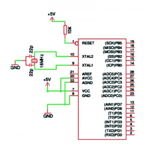
The configuration of the micro ATmega328P needs, in addition to the power (+5 VDC to pins 7 and 20, GND to pins 8 and 22), a 16-MHz crystal between pins 9 and 10, two 22 pF ceramic capacitors from between these pins and GND, a 10 k Ω resistor between pin 1 and +5 VDC for pull-up the reset line.
Anyone knows that it is necessary program Arduino uploading a sketch via USB, using the software called IDE and the operation is quite simple.
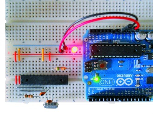
We can see a screenshot of the IDE with an Arduino sketch loaded and UNO during the receipt of the sketch (notice the yellow LED on).
The technique will test allows the use of a board Arduino as ISP Programmer.
We start with the list of required materials:
• Arduino Uno / Duemilanove (will be used as a programmer);
• ATmega328P chip (chip to be programmed);
• Breadboard and jumper;
• a crystal of 16 MHz, two ceramic capacitors from 22 pF, a resistance of 10 K Ω 1/4 W, a resistance of 560 Ω 1/4 W LED 3 or 5 mm;
• seven male-male jumper wires.
A resistance of 120 Ω 1/4 of watts, and an electrolytic capacitor or tantalum from 10 uF 10 ÷ 16 volts.
Now we prepare our target circuit and first of all insert the chip on the Breadboard, these are the connections to make:
• through the jumper to be Breadboard connect pins 7 and 20 of the chip to the positive supply line (+5 volts);
• in the same way we connect the pins 8 and 22 of the chip to the ground line supply (GND);
• connect pin 1 of the chip to the +5 V line through the resistor of 10 k Ω;
• insert the crystal to the pins 9 and 10 of the chip;
• insert the two 22 pF ceramic capacitors; both must have a leg connected to GND, while the other will serve to connect a capacitor to pin 9 and the other to pin 10 of the chip;
• insert one end of resistor 560 Ω at the pin 19 and the other end into an empty spot on the breadboard, and to this end we connect the anode LED(the longer pin) , whose other end (cathode) goes to GND;
At this point we can connect to the Arduino Breadboard using jumper cables under the following matches:
• Arduino pin 10 goes to pin 1 of the chip;
• Arduino pin 11 goes to pin 17 of the chip;
• pin 12 of Arduino is connected to pin 18 of the chip;
• pin 13 to Arduino pin 19 goes on the chip;
• the +5 V pins of Arduino goes to the positive supply line of the breadboard;
• any of the three GND pin of Arduino goes to the ground line of the breadboard.
Now look the software to reveal the “trick” that sends a sketch, using the IDE, to the chip on the Breadboard, bypassing Arduino that will play the role of Programmer ISP.
What we need to do is create a virtual board, starting from the original (corresponding to the model we are using Arduino) and making some simple but essential changes. We must first locate the file that is boards.txt containing all information relating to the various boards that the IDE shows us when we execute the command Tools->Board. Typically this file is located in the folder of the IDE software, the path X: \ mypath \ arduino-xxx \ hardware \ arduino, where X is the letter that indicates the logical drive and myPath the folder or location containing the program (xxx indicates the version of the program).
Now open the file with Notepad and see a long series of lines arranged in groups separated by a line consisting of a repetition of the symbol “#”,each group representing a different board. The lines are identified by the initial code, the same for all, but different for the board, the name that will appear in the submenu Tools->Board is inserted in the first row in the group.
The code is represented by the word “uno” which is at the beginning of each line.
The line containing the word “name” (usually the first) is followed by “=” and then the name that the board will have in the IDE.
 Other information that concern us are:
• uno.upload.maximum_size = 32256: Sets the maximum capacity of flash memory that we can use in practice from 32 Kbytes of Flash which has the total ATmega328P we must subtract the space occupied by the bootloader, for the Arduino Uno is 512 byte;
• uno.bootloader.low_fuses = 0xff; uno.bootloader.high_fuses = 0xde; uno.bootloader.extended_fuses = 0x05; these three lines are the “fuse”, are used to set the behavior of the chip and are expressed with hexadecimal values;
• uno.build.f_cpu = 16000000L: This line must correspond to the clock frequency for which the chip has been set, by means of the fused, expressed in Hz, 1 Hz 6,000,000 correspond to 16 MHz, precisely the frequency of the quartz or, more precisely, the present external oscillator to Arduino UNO; this value is used as a reference for timing controls of the software, such as delay () and millis ().
For more detail: Arduino ISP (In System Programming) and stand-alone circuits
- How can I use all flash memory on an ATmega328P?
You can remove the bootloader by programming the chip directly using an Arduino as an ISP programmer. - What is the purpose of the bootloader on an Arduino UNO?
The bootloader verifies the presence of a sketch upon power-on or reset and communicates with the IDE to load programs. - Which pins connect to +5V and GND on the ATmega328P?
Pins 7 and 20 connect to +5V, while pins 8 and 22 connect to GND. - How do I configure the clock frequency in the boards.txt file?
Set the line uno.build.f_cpu to 16000000L to match the 16 MHz external oscillator frequency. - What happens if I subtract the bootloader space from the total flash?
You increase the available memory for your code; the Arduino Uno bootloader occupies 512 bytes out of the 32 Kbytes total. - How do I connect the LED in the target circuit?
Connect one end of a 560 Ω resistor to pin 19, then connect the LED anode to that point and the cathode to GND. - Where is the boards.txt file typically located?
It is found in the IDE software folder at the path X:mypatharduino-xxxhardwarearduino. - Can I program chips without a bootloader using this method?
Yes, this technique allows you to use new ATmega chips cheaper than those with bootloaders by bypassing the bootloader requirement.