Bored of blinky lights that blink in response to time?
Make them blink with space instead!
This instructable shows a quick method for connecting LED tree decorations to a Geiger counter via arduino, so that the lights blink between different strings each time radiation is detected.
It’s nicer to think of this as “cosmic rays” than some of the other possibilities…

What you’ll need:
- A Geiger counter with pulse output (I’m using the Gieger counter from MightyOhm)
- A few strings of battery-operated LED decorations (I’m using stars and snowflake decorations from Poundland, ‘cos you gotta love dem luminous spheres of plasma and dem frozen supercooled cloud droplets)
- Arduino-based microcontroller (either a proper development board, or I’m using a stripboard bare bones version)
- Female header (two or three sockets’ worth)
- Batteries/alternative power supply for your Geiger counter and Arduino
- Assortment of connecting wires (either jumper leads or multi-core stuff to solder)
- Soldering equipment, wire cutters, wire strippers etc.
- Maybe a spare LED for testing, insulation tape…
Step 1: The Geiger counter
The Geiger counter from MightyOhm includes a pulse output :
The PULSE connector (J6) has the following pinout:
1. VCC (nominally 3V)
2. pulse output – a short (100us) active high pulse every time the geiger tube fires
3. GND
We need to connect the GND pin (the one on the right) with a ground pin on our arduino and the pulse output (middle) with a pin on the arduino so we can detect the detections.
Cut 3 sockets’ worth of female header. (You can get away with two if you have to.)
Cut yourself two lengths of wire long enough to reach between your Geiger counter and your arduino. It’s helpful to have two different colours, but not essential. I’m something of a traditionalist and have used black for ground and red for the pulse output…
Solder the ground wire to one of the outer pins and the pulse wire to the middle pin.
This assembly should fit nicely onto the male pins on the Geiger counter:
Step 2: The arduino
Now we need to connect the other end of those wires to the microcontroller.
I grabbed an old stripboard version I had lying around.
There are various instructions available online for making these, I remember referring to the Standalone Arduino / ATMega chip on breadboard instructable and the ITP Setting up an Arduino on a breadboard tutorial.
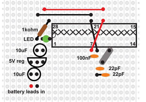
It was a lot of learning ago, so don’t copy my wiring! If I were to start from scratch I’d do it like the schematic included in the images…
Connect the pulse output wire to pin 12 and ground to GND
Step 3: Test it
Now’s a good time to check the arduino is reading the pulses from the Geiger counter…
I’m still learning the basics of coding. Mostly from Garry. He showed me how to do this bit!
Connect an LED between pin 13 and gnd of the microcontroller (if your board doesn’t already have an integrated one).
Upload the following code to your microcontroller:
const int geigerPin = 12; // connected to pulse out of Geiger counter, grounds connected too
void setup() {
pinMode(geigerPin, INPUT);
}
int led = LOW;
void loop() {
int val = digitalRead(geigerPin);
while (val == LOW) {
// do what ever happens when there is no signal
val = digitalRead(geigerPin);
}
// got the start of a pulse, so do something appropriate
// toggle the LED so that you can see things working
digitalWrite(13, led);
led = !led;
while (val == HIGH) {
// wait for pulse to end, 100us is a long time for an Arduino
val = digitalRead(geigerPin);
}
// pulse finished
}
Power up the Geiger counter and the arduino, check they are connected properly, and you should see the LED toggle on or off each time the Geiger counter detects some radiation.
Assuming all is now working as it should, we’re going to need MORE LEDS!
For more detail: Geiger counter triggered LED decorations