Arduino is an amazing tool for Makers, and as I got back into Nerf and started modding, I began to wonder what I could do with Arduindo to help determine the effect of modifications. Take a look at any older Nerf video and you will find a kid firing darts on their lawn over a tape measure. Take a look at any recent Nerf video, and you will see them shooting darts through an expensive ballistic chronograph. Why not apply Arduino to help us with Nerf mods, both in measuring performance and in controlling operation?
Using this project to measure dart speed as an example, I looked at the effect of removing the air restrictor and adding a stronger spring to a thrift-store Modulus Modulator. Either mod by itself equated to 20 to 25% improvement. Together, however, an exponential increase of almost 80%!
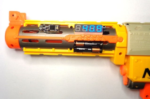
The cover photo is just a teaser example of a chrongraph integrated with a barrel attachment and display. We will first focus on detection portion and get the readings on a serial console. And yes, this poor old unmodified thrift-store Recon is shooting a miserable 40 fps. Once we know what we are starting with we can start modding to see the effects . ..
There are already a number of cool projects like this out there. My goal for this one was to make it fundamental enough to understand and easy enough for a beginner to accomplish. You’ll have to judge if I succeeded, or let me know how to make it better.
Step 1: How Does It Work?

There are a number of methods to measure the speed of an object. We want easy, reliable, and inexpensive. My choice is an infrared emitter detector pair. The microcontroller will sense when an object enters the beam, and when the object leaves the beam. If we know the length of the object, and measure the time it takes, we have all the ingredients needed calculate velocity.
The photo transistor works as a switch, but instead of a signal being applied to the base to allow current to flow from the collector to the emitter, light is applied. The dark cover means only infrared light will work. We are using a small resistor to pull-up the signal to 5 volts, so when the IR light is detected, current flows through the transistor, allowing the signal to fall toward 0 volts. It is a bit counter intuitive, but it works. Learn more about how transistors work at https://www.electronics-tutorials.ws/transistor/tran_4.html.
Step 2: Parts and Tools
To start with, we just want to wire something up to test it on the bench. Later, we can integrate it into a stand-alone solution ready for the battlefield.
Parts:
- Arduino Uno or compatible microcontroller, recommend:
- Adafruit Metro, https://www.digikey.com/short/pzf5rv) or
- Adafruit ItsyBitsy, https://www.digikey.com/short/pz2pc0 (doesn’t have headers, so wires will have to be soldered to it).
- 1 ea., NPN Photo Transistor
- Lite-On LTR-4206E, https://www.digikey.com/short/pzf5cn or
- Everlight PT204-6B, https://www.digikey.com/short/jw9ht0
- 1 ea., IR Emittor
- Lite-On LTE-4206, https://www.digikey.com/short/pzf57f or
- Everlight IR1503, https://www.digikey.com/short/jw9m1r
- Resistors
- 100 ohm 1/8 or 1/4W generic, https://www.digikey.com/short/q72818
- 10K ohm 1/8 or 1/4W generic, https://www.digikey.com/short/7thw1q
- Heat shrink assortment
- 12″ Jumper wire assortment, Adafruit 1955, https://www.digikey.com/short/pzf5pb
Tools:
- Soldering iron, solder, safety glasses
- Wire snips (recommend Hakko CHP-170, https://www.digikey.com/short/ptnm3p)
- Wire stripper (recommend Hakko CSP-30-1, https://www.digikey.com/short/pzf55b)
- Hot air gun (recommend SparkFun Heaterizer, https://www.digikey.com/short/pzf5mj)
- Hot glue gun
Step 3: Let’s Begin . . .
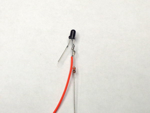
The photo transistor is the dark package.
The short leg is the collector. We are going to attach the sensor wire and a 10K ohm pull-up resistor to it.
- Select a jumper wire with a color other than black or red (orange in the photo looks red).
- Cut one end off near the terminal and strip about 1/2″ of insulation off.
- Twist the sensor wire with the 10K resistor around the short leg and solder them together.
- Slide a piece of heat shrink over the wire and resistor, leaving the resistor leg sticking out, and shrink.
Source: Arduino for Nerf: Ballistic Chronograph