Summary of Read a Potentiometer With Arduino’s Analog Input
This tutorial shows how to read a potentiometer (rotating variable resistor) with an Arduino analog input to control an LED. It explains wiring on a solderless breadboard, connecting potentiometer outer pins to 5V and GND and the center wiper to analog pin A0, plus an LED with series resistor to digital pin 13 and ground. It also suggests using Tinkercad Circuits for simulation and provides block-code to map potentiometer readings to LED blink rate.
Parts used in the Read a Potentiometer With Arduino's Analog Input:
- Arduino Uno board
- USB cable
- Solderless breadboard
- LED
- Resistor (100 to 1K ohms)
- Potentiometer
- Breadboard wires (jumper wires)
Let’s learn how to read a potentiometer, a type of rotating variable resistor, using Arduino’s analog input! We’ll connect up a simple circuit using a solderless breadboard and use some simple Arduino code to control a single LED.
So far you’ve learned to control LEDs with Arduino’s output, and you learned to detect a pushbutton’s state (on or off) with digital input. In this lesson, we’ll sense the gradually changing electrical signal from turning the potentiometer with Arduino’s analog inputs, located on the opposite side of the board from the digital i/o (input/output) pins. These special analog pins are connected to the Arduino’s analog to digital converter (ADC), which converts an incoming analog signal between 0V and 5V into a range of numbers from 0-1023 (zero counts as a value).
Explore the sample circuit embedded here clicking Start Simulation and clicking to turn the potentiometer. To optionally build the physical circuit, gather up your Arduino Uno board, USB cable, solderless breadboard, an LED, resistor (any value from 100-1K), potentiometer, and breadboard wires.
You can follow along virtually using Tinkercad Circuits. You can even view this lesson from within Tinkercad (free login required)! Explore the sample circuit and build your own right next to it. Tinkercad Circuits is a free browser-based program that lets you build and simulate circuits. It’s perfect for learning, teaching, and prototyping.
Step 1: Build the Circuit
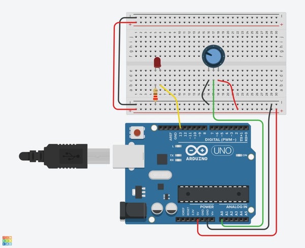
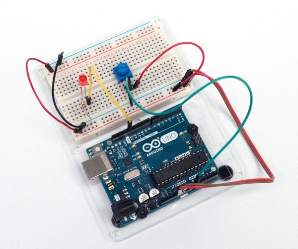
Take a look at the breadboard circuit pictured. It can be useful to look at a free-wired version of this sample circuit for comparison, also pictured. Remember that the breadboard rows are connected inside, so you can plug in components and wires to make quick temporary connections. You could load up a new Tinkercad Circuits window and build your own version of this circuit along side the sample.
Identify the potentiometer, LED, resistor, and wires connected to the Arduino.
Drag an Arduino Uno and breadboard from the components panel to the workplane.
Connect breadboard power (+) and ground (-) rails to Arduino 5V and ground (GND), respectively, by clicking to create wires.
Extend power and ground rails to their respective buses on the opposite edge of the breadboard by creating a red wire between both power buses and a black wire between both ground buses.
Plug the LED into two different breadboard rows so that the cathode (negative, shorter leg) connects to one leg of a resistor (anywhere from 100-1K ohms is fine). The resistor can go in either orientation because resistors aren’t polarized, unlike LEDs, which must be connected in a certain way to function.
Connect other resistor leg to ground.
Wire up the LED anode (positive, longer leg) to Arduino pin 13.
Drag a potentiometer from the components panel to the your breadboard, so its legs plug into three different rows.
Click to create a wire connecting one outer potentiometer leg to power.
Connect the center leg to Arduino analog pin A0.
Create a wire connecting the other outer leg to ground.
Step 2: Code With Blocks
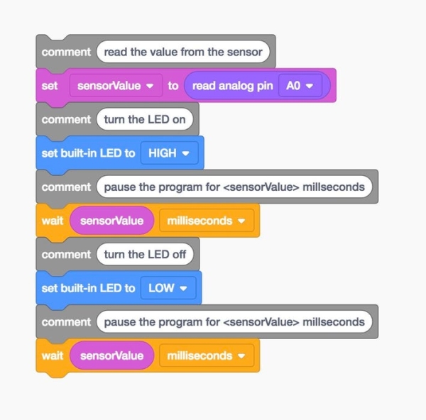
Let’s use the code blocks editor to listen to the state of the potentiometer, then flash an LED at a rate related to the variable resistance of the potentiometer.
Read more: Read a Potentiometer With Arduino’s Analog Input
- How do I connect the potentiometer to the Arduino?
Connect one outer leg to 5V, the other outer leg to GND, and the center wiper leg to analog pin A0. - Can I simulate this circuit instead of building it physically?
Yes, you can use Tinkercad Circuits to build and simulate the sample circuit. - What value resistor should I use with the LED?
Use any resistor value from 100 to 1K ohms. - Which Arduino pin is the LED connected to in the example?
The LED anode is connected to digital pin 13. - How does Arduino read the potentiometer value?
Arduino reads the potentiometer via its analog input A0 which uses the ADC to convert 0–5V into values from 0 to 1023. - Does the resistor orientation matter when wiring it to the LED?
No, resistor orientation does not matter because resistors are not polarized. - What does turning the potentiometer do in the circuit?
Turning the potentiometer changes its resistance and thus the analog voltage at A0, which the code maps to the LED blink rate.