Arduino Fixed-point Vehicle Proximity Detector

This is the high-tech version of hanging a tennis ball from the ceiling from a piece of string.  Of course, if you have two different types of vehicles, that tennis ball isn’t going to land in the same place on both of them.  This project can prevent hundreds of dollars in dry-wall repair and bicycle crank replacements, not to mention the shame of poor parking skills.

In this instructable, we’ll be making everything “plug-n-play.”  This gives us three advantages.  First off, you don’t have to worry about frying electronics with poor soldering technique.  Second, modular impermanence means you can use almost all the parts again just by pulling them out of their sockets.  Third, good Arduino hardware and breadboard practices are oriented towards pin-plugging, so we’ll include a technique that can be adapted to almost anything you want to plug into your Arduino (servos, motors, sensors, even speakers.)

Arduino Fixed-point Vehicle Proximity Detector

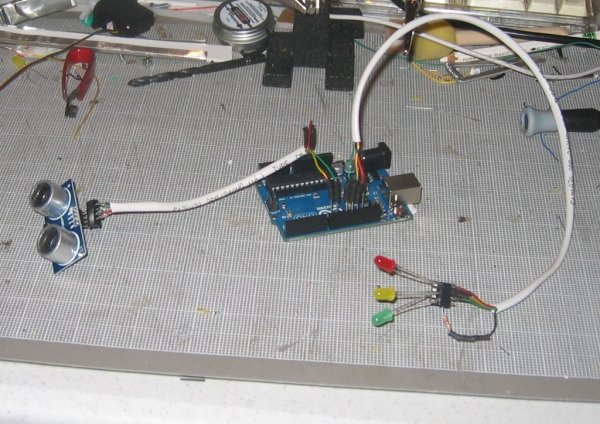
To begin, gather your materials:
-An Arduino UNO board.  (Duemillanoves and Megas should work just as well, I just haven’t tested them.)
-An HC-SR04 Ultrasonic Ping sensor.  There are two types commonly available-you want the four pin type for this tutorial.
-One Red LED
-One Yellow LED
-One Green LED
-Two 8-pin Din sockets
-One 180Ω Resistor
-24 gauge solid 2-twisted Pair Telephone hookup wire.
-Eight #17 stick pins
-about 4 inches of 1/8″ heat-shrink tubing.

Tools:
-Soldering Iron and solder
-Angle snips
-Heat source for the heat shrink tubing (candle lighters or paint-remover guns work well.)
-Needle nose pliers and a “helping hand” work stand never hurt

Step 1: Step One:Ground the Current Limiting Resistor

First, take one of the 8-Pin DIP sockets and your 180Ω resistor.  Place the resistor across three pins of the socket and solder it to each pin.  (It won’t hurt anything to solder it to all 4.  Also, a resistor will probably stand up to the soldering without the heat-sink in the photo.  It’s just good practice and it holds it in place well.)

Step 2: Step 2:Add Color Coded Voltage Feed Wires

Take a length of phone hook up wire (the length should be determined more or less by how high above where you plan to mount your Arduino you want your indicator lights to be) and strip about 1 1/2″-2″ of the outer insulator off of it.  Then strip about 1/8″ of the insulator off of each of the red, green and yellow wires.  We’re going to keep everything color coded and consistent here, and phone hookup wire is a great way of doing that.    Solder one wire to each pin across from the three pins that you soldered the resistor to so that the yellow wire is in the middle (you may want to heat-shrink at least the yellow wire.)

About The Author

Ibrar Ayyub

I am an experienced technical writer holding a Master's degree in computer science from BZU Multan, Pakistan University. With a background spanning various industries, particularly in home automation and engineering, I have honed my skills in crafting clear and concise content. Proficient in leveraging infographics and diagrams, I strive to simplify complex concepts for readers. My strength lies in thorough research and presenting information in a structured and logical format.

Follow Us:
LinkedinTwitter

Leave a Comment

Your email address will not be published. Required fields are marked *

Scroll to Top