Summary of ATtiny programming with Arduino
This article guides users on programming an ATtiny85/45 microcontroller using an Arduino as an ISP programmer. It details the necessary hardware, wiring connections between the Arduino and ATtiny pins, and the software setup required to upload sketches. The guide emphasizes that the Arduino configuration is temporary, allowing the board to be reused for other projects after programming the chip.
Parts used in the ATtiny Programming Project:
- Arduino
- AT tiny 85/45
- Bread board or 8 pin shield
- Bread board jumper wires
- Led- 5
- 330 ohm resistor-5
- 1uf 50V electrolytic capacitor
After this Instructable you should be able to program an A Ttiny85/45 with an arduino. It may sound complex but it really isn’t. After doing some research I could not find to much info on how this could be done. I however did find http://www.instructables.com/id/Program-an-ATtiny-with-Arduino/. This Instructable is my interpretation of what I learned from Randy.
Step 1: Things you will need
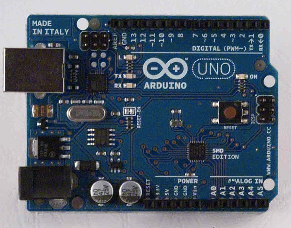
Arduino
AT tiny 85/45 – available from Mouser 556-ATTINY85-20PU Need more info on the AT tiny check out the data sheet here.
Bread board ( or the 8 pin shield from Instructables )
Bread board jumper wires
Led- 5
330 ohm resistor-5
1uf 50V electrolytic capacitor
Step 2: Set up
You will be using the following arduino pins (see pic)
5V +
5V Ground x2
10
11
12
13
Reset
Wire up the bread board with the jumper wires as follows or see pic:
Note: be sure to not the dimple direction.
ATtiny pin# 1 to arduino pin# 10
ATtiny pin# 4 to arduino 5v ground
ATtiny pin# 5 to arduino pin# 11
ATtiny pin# 6 to arduino pin# 12
ATtiny pin# 7 to arduino pin# 13
ATtiny pin# 8 to Arduino 5v +
Now lets move onto adding our leds. Add the leds to the bread board as see in the pic keeping in mind the polarity of the leds.
Add the resistors to the positive side ( side without the flat part ) each led with get a resistor. Take some jumper wires from the resistors and connect them to the following ATtiny pins.
ATtiny pin# 5 this will be programmed as pin 0 in the sketch
ATtiny pin# 6 this will be programmed as pin 1 in the sketch
ATtiny pin# 7 this will be programmed as pin 2 in the sketch
ATtiny pin# 2 this will be programmed as pin 3 in the sketch
ATtiny pin# 3 this will be programmed as pin 4 in the sketch
Step 3: Setting up the arduino to program
Setting up the arduino to program is not a permanent thing. All this will do is load a sketch that will allow you to program the chip then when you want to use the arduino you simply change the sketch.
Fist things first you will need the program, down load it by clicking attiny45_85.zip be sure that you are using arduino program version 0022.
AT tiny 85/45 – available from Mouser 556-ATTINY85-20PU Need more info on the AT tiny check out the data sheet here.
Bread board ( or the 8 pin shield from Instructables )
Bread board jumper wires
Led- 5
330 ohm resistor-5
1uf 50V electrolytic capacitor
For more detail: ATtiny programming with Arduino
- How do I wire the ATtiny pins to the Arduino?
Connect ATtiny pin 1 to Arduino pin 10, pin 4 to ground, pin 5 to pin 11, pin 6 to pin 12, pin 7 to pin 13, and pin 8 to 5V +. - Can I use a breadboard shield instead of a standard breadboard?
Yes, the article mentions using the 8 pin shield from Instructables as an alternative to a breadboard. - What is the best way to connect the LEDs to the circuit?
Add resistors to the positive side of each LED and connect them to ATtiny pins 5, 6, 7, 2, and 3. - Does setting up the Arduino to program require permanent changes?
No, the setup loads a sketch temporarily; you simply change the sketch back when you want to use the Arduino normally. - Which Arduino version should I use for this project?
You must be using Arduino program version 0022. - Where can I download the required program file?
The program is available by downloading attiny45_85.zip. - How are the ATtiny pins mapped in the code sketch?
ATtiny pin 5 is programmed as pin 0, pin 6 as pin 1, pin 7 as pin 2, pin 2 as pin 3, and pin 3 as pin 4. - What components are needed for the power supply connection?
You need a 1uf 50V electrolytic capacitor along with the ATtiny and Arduino connections.