Summary of Arduino + fischertechnik TX-C – Connecting I2C True Colour Sensor
This article details a 12-month project to solve industrial colour reading issues by integrating an I2C colour sensor with a fischertechnik controller. The author evolved from basic LED setups to a digital solution using an Arduino and an Avago ADJD-S371-Q999 sensor, overcoming communication challenges via logic level converters and opto-isolators to bridge the gap between the Arduino and the Robo TX controller.
Parts used in Colour Reading Project:
- Inventor's Kit for Arduino (Sparkfun KIT-10173)
- Logic Level Converter (Sparkfun BOB-08745)
- Color Light Sensor Evaluation Board (Sparkfun SEN-08663) based on Avago ADJD-S371-Q999
- Opto-isolator Breakout (Sparkfun BOB-09118)
- Robo TX controller
- Switch
- Three lamps
Colour reading is a real issue for industrial models.
I’ve been working on it for more than 12 months now, since December 2009.
After many months of hard work,
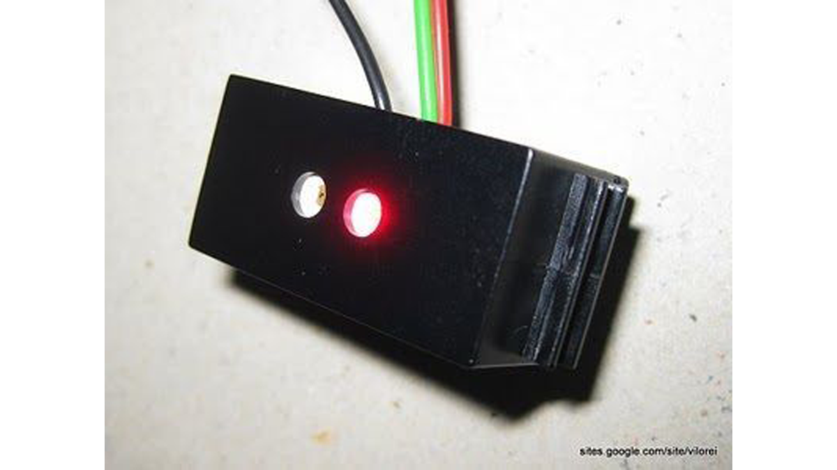
• starting with the standard colour reader (season 1 ) with features a red LED,
• adding extra light from bulb lamps (season 2 ),
• using a powerful external white LED lamp (season 3 ),
• changing the built-in standard red LED for a white LED (season 4 ),
• I decided to go digital with an I2C 4 channels 10 bits sensor.
There are two challenges:
• manage the I2C sensor on Arduino,
• pass the information on to the fischertechnik controller.
Step 1: Technical Solution
On the Arduino side, I’m using:
• Inventor’s Kit for Arduino (Sparkfun KIT-10173 )
• Logic Level Converter (Sparkfun BOB-08745 )
• Color Light Sensor Evaluation Board (Sparkfun SEN-08663 ) based on Avago ADJD-S371-Q999
• Opto-isolator Breakout (Sparkfun BOB-09118 )
The Avago ADJD-S371-Q999 is a four channels, red, green, bleu and clear, 10 bits colour sensor with built-in white LED.
On the fischertechnik side, I’m using
• a Robo TX controller (here or there )
• one switch
• three lamps
The Robo TX controller is I2C capable but, as at today, this feature is under development. So connecting the Avago sensor directly can’t work!
See here for a short comparison between the Arduino and the Robo TX controller.
Step 2: Arduino Side – Hardware
I use the following colours:
• red cable for 5V
• black cable for ground
• blue cable for I2C SCL
• green cable for I2C SDA
• white cable for D0
• yellow cable for D1
I provide the step-by-step cabling:
1• empty board
2• power and I2C connections between Arduino and logic level connector
3• power connections between colour sensor and logic level convertor and 5V for the built-in LED
4• I2C connections between colour sensor and logic level convertor
5• digital connections between Arduino and opto-isolator
6• cables from opto-isolator to the fischertechnik TX controller
For more detail: Arduino + fischertechnik TX-C – Connecting I2C True Colour Sensor
- How long did the author work on this project?
The author worked on it for more than 12 months since December 2009. - What sensor was chosen for the digital solution?
An I2C 4 channels 10 bits sensor, specifically the Avago ADJD-S371-Q999. - Why could the Avago sensor not connect directly to the Robo TX controller?
The Robo TX controller is I2C capable but that feature was under development at the time. - What components are required on the Arduino side?
The Inventor's Kit, Logic Level Converter, Color Light Sensor Evaluation Board, and Opto-isolator Breakout. - What colours are used for the cables in the wiring setup?
Red for 5V, black for ground, blue for SCL, green for SDA, white for D0, and yellow for D1. - What challenge does the opto-isolator help solve?
It helps pass information from the Arduino to the fischertechnik controller. - Does the Avago ADJD-S371-Q999 have a built-in light source?
Yes, it has a built-in white LED. - What were the initial methods tried before the digital solution?
Standard red LED, extra bulb lamps, external white LED lamp, and changing the standard red LED for a white LED.