Summary of Inverted Pendulum: Control Theory and Dynamics
The article explains building an inverted-pendulum on a cart to demonstrate dynamics and control theory. It covers the problem, equations of motion, closed-loop PID control, classroom implementation, required parts, and step-by-step assembly (gantry rollers and stepper drive). It emphasizes hands-on learning, 3D-printed components, and using sensors and a microcontroller to stabilize the pendulum.
Parts used in the Inverted Pendulum:
- Arduino compatible board (recommend Uno)
- Nema17 stepper motor
- Stepper motor driver (recommend A4988)
- MPU-6050 Six-Axis gyro + accelerometer
- 12v 10A power supply (3A minimum acceptable)
- 16 bearings (skateboard bearings used)
- 2 GT2 pulleys
- GT2 belt
- Approximately 2.4 meters of 1.5-inch PVC pipe
- Assorted 4mm nuts and bolts
- 3D printed parts: 2 Gantry Roller
- 3D printed parts: 4 End Caps
- 3D printed parts: 1 Stepper Bracket
- 3D printed parts: 2 Idle Pulley Bearing Holder
- 3D printed parts: 1 Pendulum Holder
- 3D printed parts: 2 Belt Attachment
- 3D printed parts: 1 Pendulum Bearing Holder (a)
- 3D printed parts: 1 Pendulum Bearing Holder (b)
- 3D printed parts: 1 Pulley Hole Spacer
- 3D printed parts: 4 Bearing Hole Spacer
- 3D printed parts: 1 Gantry Plate
- 3D printed parts: 1 Stepper Holder Plate
- 3D printed parts: 1 Idle Pulley Holder Plate
- 3D printed parts: 1 Pendulum(a)
- 3D printed parts: 1 Pendulum(b)
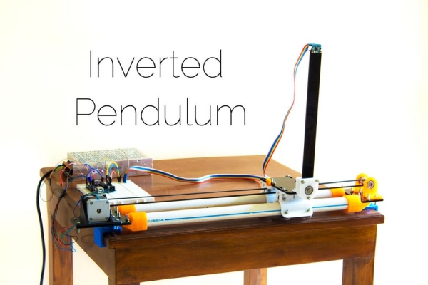
The inverted pendulum is a classic problem in dynamics and control theory that is generally elaborated in high-school and undergraduate physics or math courses. Being a math and science enthusiast myself, I decided to try and implement the concepts that I learned during my classes to build an inverted pendulum. Applying such concepts in real life not only helps strengthen your understanding of the concepts but also exposes you to a whole new dimension of problems and challenges that deal with practicality and real-life situations that one can never encounter in theory classes.
In this instructable, I will firstly introduce the inverted pendulum problem, then cover the theory aspect of the problem, and then discuss the hardware and software required to bring this concept to life.
I suggest you watch the video that is attached above while going through the instructable which will give you a better understanding.
And finally, please don’t forget to drop a vote in the ‘Classroom Science Contest’ if you liked this project and feel free to leave any questions in the comment section below. Happy making! 🙂
Step 1: The Problem
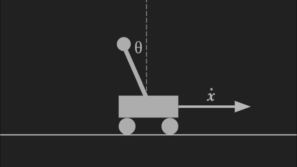
The inverted pendulum problem is analogous to balancing a broom or a long pole on the palm of your hand, which is something most of us have tried as a kid. When our eyes see the pole falling to a certain side, they send this information over to the brain which performs certain computations and then instructs your arm to move to a certain position with a certain velocity to counter the pole’s movement, which would hopefully bring the tipping pole back up to vertical. This process is repeated several hundred times a second which keeps the pole completely under your control. The inverted pendulum functions in a similar manner. The aim is to balance a pendulum upside down on a cart that is allowed to move about. Instead of eyes, a sensor is used to detect the position of the pendulum which sends the information over to a computer which performs certain computations and instructs actuators to move the cart in a way to make the pendulum vertical again.
Step 2: The Solution

This problem of balancing a pendulum upside down requires insight into the movements and forces that are at play in this system. Eventually, this insight will allow us to come up with “equations of motion” of the system which can be used to compute relations between the output that is going to the actuators and the inputs coming from the sensors.
The equations of motion can be derived in two ways depending on your level. They can either be derived using the basic laws of Newton and some high school level mathematics or using Lagrangian mechanics which is generally introduced in undergraduate physics courses. (Note: Deriving the equations of motion using Newton’s laws is simple but tedious whereas using Lagrangian mechanics is much more elegant but requires the understanding of Lagrangian mechanics although both approaches eventually lead to the same solution).
Both approaches and their formal derivations are usually covered in high school or undergraduate classes on math or physics, although they can easily be found using a simple google search or by visiting this link. Observing the final equations of motion we notice a relation between four quantities:
- The angle of the pendulum to the vertical
- The angular velocity of the pendulum
- The angular acceleration of the pendulum
- The linear acceleration of the cart
Where the first three are quantities that are going to be measured by the sensor and the last quantity is going to be sent to the actuator to perform.
Step 3: Control Theory
Control theory is a subfield of mathematics that deals with controlling and operating dynamical systems in engineered processes and machines. The objective is to develop a control model or a control loop to generally achieve stability. In our case, balance the upside down pendulum.
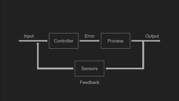
There are two main types of control loops: open loop control and closed loop control. When implementing an open loop control, the control action or the command from the controller is independent of the system’s output. A good example of this is a furnace, where the amount of time that the furnace remains on is purely dependant on the timer.
Whereas in a closed loop system, the controller’s command is dependant on the feedback from the state of the system. In our case, the feedback is the angle of the pendulum with reference to the normal which determines the speed and position of the cart, therefore making this system a closed loop system. Attached above is a visual representation in the form of a block diagram of a closed loop system.
There are several feedback mechanism techniques but one of the most widely used is the proportional–integral–derivative controller (PID controller), which is what we are going to use.
Note: Understanding the workings of such controllers is very useful in developing a successful controller although explaining the operations of such a controller is beyond the scope of this instructable. In case you have not come across these types of controllers in your course there are bunches of material online and a simple google search or an online course will help.
Step 4: Implementing This Project in Your Classroom
Age Group: This project is primarily for high-school or undergraduate students, but could also be presented to younger children simply as a demonstration by giving an overview of the concepts.
Concepts Covered: The main concepts that are covered with this project is dynamics and control theory.
Time required: Once all the parts are gathered and fabricated, assembling takes 10 to 15 mins. Creating the control model requires some more time, for this, the students can be given 2 to 3 days. Once each individual student (or groups of students) have developed their respective control models, another day can be used for the individuals or the teams to demonstrate.
One way to implement this project into your classroom would be to build the system (described in following steps), while the batch is working on the subtopics of physics related to dynamics or while they are studying control systems in math classes. In this way, ideas and concepts that they come across during class can be directly implemented into a real-world application making their concepts far more clear because there is no better way to learn a new concept than by implementing it in real life.
A single system can be built, together as a class and then the class can be divided into teams, each building a control model from scratch. Each team can then demonstrate their work in a competition format, where the best control model is the one that can balance the longest and withstand nudges and pushes robustly.
Another way to implement this project in your classroom would be to make older kids (high school level or so), develop this project and demonstrate it to younger children while giving them an overview of dynamics and controls. This may not only spark interest for physics and math for the younger children but will also help the older students crystallize their concepts of the theory because one of the best ways to strengthen your concepts is by explaining it to others, especially younger children as it requires you to formulate your ideas in a very simple and clear manner.
Step 5: Parts and Supplies
The cart will be allowed to freely move on a set of rails giving it a single degree of freedom. Here are the parts and supplies required to make the pendulum and the cart and rails system:
Electronics:
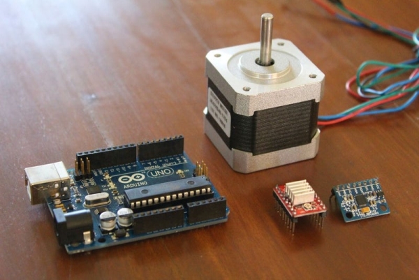
- One Arduino compatible board, any will work. I recommend an Uno in case you are not too experienced with electronics because it’ll be simpler to follow along.
- One Nema17 stepper motor, which will function as the actuator for the cart.
- One stepper motor driver, once again anything will work, but I recommend A4988 stepper motor driver because it will just be simpler to follow along.
- One MPU-6050 Six-Axis (Gyro + Accelerometer), which will detect the various parameters such as angle and angular velocity of the pendulum.
- One 12v 10A power supply, 10A is actually a slight overkill for this specific project, anything above 3A will work, but having the possibility to draw extra current allows for future development where more power may be required.
Hardware:
- 16 x bearings, I used skateboard bearings and they worked great
- 2 x GT2 pulleys and belt
- About 2.4 meters of 1.5-inch PVC pipe
- Bunch of 4mm nuts and bolts
Some of the parts that were used in this project were also 3D printed, therefore having a 3D printer will be very useful, although local or online 3D printing facilities are commonly available.
The total cost of all parts is just a little less than 50$ (excluding the 3D printer)
Step 6: 3D Printed Parts
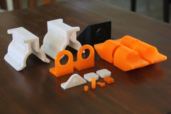
Some of the parts of the cart and rails system had to be custom made, so I used Autodesk’s free to use Fusion360 to model the cad files and 3D print them on a 3D printer.
Some of the parts that were purely 2D shapes, such as the pendulum and the gantry bed, were laser-cut as it was much quicker. All the STL files are attached below in the zipped folder. Here is a complete list of all the parts:
- 2 x Gantry Roller
- 4 x End Caps
- 1 x Stepper Bracket
- 2 x Idle Pulley Bearing Holder
- 1 x Pendulum Holder
- 2 x Belt Attachment
- 1 x Pendulum Bearing Holder (a)
- 1 x Pendulum Bearing Holder (b)
- 1 x Pulley Hole Spacer
- 4 x Bearing Hole Spacer
- 1 x Gantry Plate
- 1 x Stepper Holder Plate
- 1 x Idle Pulley Holder Plate
- 1 x Pendulum(a)
- 1 x Pendulum(b)
In total there are 24 parts, which don’t take too long to print as the parts are small and can be printed together. In the course of this instructable, I will be referring to the parts based on the names in this list.
Step 7: Assembling the Gantry Rollers
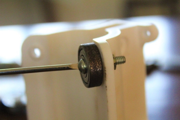
The gantry rollers are like the wheels for the cart. These will roll along the PVC track which will allow the cart to move smoothly with minimal friction. For this step, grab the two 3D printed gantry rollers, 12 bearings and a bunch of nuts and bolts. You will require 6 bearings per roller. Attach the bearings to the roller using the nuts and bolts (Use the pictures as a reference). Once each roller is made, slide them onto the PVC pipe.
Step 8: Assembling the Drive System (Stepper Motor)
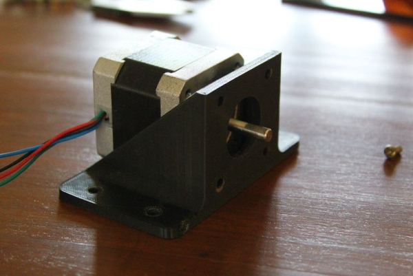
The cart is going to be driven by a standard Nema17 stepper motor. Clamp the motor into the stepper bracket using the screws that should have come as a set with the stepper. Then screw the bracket onto the stepper holder plate, align the 4 holes on the bracket with the 4 on the plate and use nuts and bolts to secure the two together. Next, mount the GT2 pulley onto the shaft of the motor and attach the 2 endcaps to the stepper holder plate from the bottom using more nuts and bolts. Once done, you can slide the endcaps onto the pipes. In case the fit is too right instead of forcing the endcaps onto the pipes, I recommend sanding the inner surface of the 3D printed endcap until the fit is snug.
Read more: Inverted Pendulum: Control Theory and Dynamics
- What is the inverted pendulum problem?
The inverted pendulum is balancing a pendulum upside down on a cart that can move, analogous to balancing a broom on your hand. - What sensors are used to detect pendulum motion?
The project uses an MPU-6050 six-axis gyro and accelerometer to detect angle and angular velocity. - What actuator is recommended to move the cart?
A Nema17 stepper motor is used as the actuator to drive the cart. - What control method is used to balance the pendulum?
A closed-loop proportional–integral–derivative controller (PID) is used. - What microcontroller is suggested for this project?
An Arduino compatible board is recommended, with the Uno suggested for simplicity. - How many bearings are needed for the gantry rollers?
Six bearings per gantry roller are used, totaling 12 for two rollers; the parts list uses 16 bearings overall. - Are any 3D printed parts required?
Yes, multiple custom parts are 3D printed, including gantry rollers, end caps, brackets, pendulum holders, spacers, plates, and pendulum parts. - How much time is required to assemble and develop the control model?
Assembling takes 10 to 15 minutes once parts are ready; developing the control model can take 2 to 3 days, plus a day for demonstrations. - What power supply is recommended?
A 12v 10A power supply is recommended, though anything above 3A will work for this project.