
Summary of Turing Alarm for Arduino
This project is a Turing-style alarm clock built with an Arduino microcontroller that requires users to solve math problems to turn off the alarm. It features a DS1307 real-time clock, a serial LCD for display, a buzzer for alerts, and five buttons for menu navigation. An optional MOSFET circuit allows for 12V light dimming control. The build involves soldering headers, connecting components to a PCB or breadboard, and programming the logic within a project box.
Parts used in the Turing Alarm Clock:
- Arduino board (Uno or Pro Mini)
- DS1307 RTC
- SparkFun Serial LCD 16x2
- Small 12mm buzzer (2.048 kHz)
- 5 SPST panel mount momentary switches
- 10k pull-down resistors
- DC jack panel mount
- Project box
- Mounting screws and nuts
- Female and male headers
- 10K slide potentiometer (optional)
- N-channel MOSFET (optional)
- Blank copper PCB (optional)
NOTE: This Instructable is currently incomplete. I will finish it before September 19.
I started this project after seeing Nick Johnson’s Turing Alarm clock. I found that the PIC chip he used was a little too advanced for me, so I decided to use the Arduino microcontroller. The original project by Nick Johnson can be found on his blog here . All credits for the idea goes to Nick.
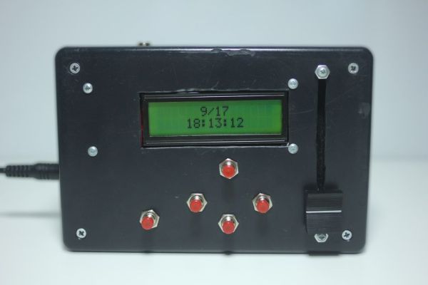
The turing alarm forces you to solve math problems when you wake up. If you get the math problem correct, the alarm stops, and if you don’t, you will have to solve another one. My version also includes a 12V light dimmer using a MOSFET. A DS1307 real time clock (RTC) keeps track of the time and the menus are controlled with five buttons.
Future improvements:
Joystick control
Math problem level setting
battery backup power
two alarms
Step 1: Materials and Tools
Materials
• Arduino board
I used the Uno board for testing and the Pro Mini for the final project
• DS1307 RTC
You can use the DIP version; I used the breakout from SparkFun
• SparkFun Serial LCD 16×2 (Any serial LCD will work)
This is much easier to interface with than a parallel LCD
• Small 12mm buzzer (2.048 kHz)
• 5 SPST panel mount momentary switches
• 10k pull-down resistors
You will need seven of these
• 1 DC jack panel mount (two if you want light control)
• Project box
I used a 6 x 3 x 2″ project box from Radioshack
• Mounting screws and nuts (4-40 ½ inch)
Mount LCD and slide potentiometer
• Female and male headers
• 10K slide potentiometer
Only if you want light control
• N-channel MOSFET
Only if you want light control
• Blank copper PCB
This is optional, but it makes layout easier
Tools
• Soldering iron
• Jumper wire
• FTDI Basic board
• USB-B cable
• Drill with bit
• Dremel / rotary tool
• Ruler
• Breadboard
• Mini push-button switches for testing
• PCB etching and drilling equipment
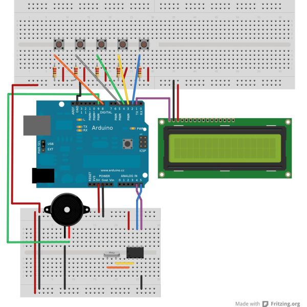
Step 2: Solder Headers
You will need to solder headers onto the RTC and the LCD. There are two sets of connections on the LCD: one is already terminated with a JST connector, and the other is empty. They both do the same thing, so pick which one you want to use. I didn’t have any JST cables so I desoldered them and attached hookup wires.
If your Pro Mini is new, you will also have to solder headers on them. Be careful with the Pro Mini because some SMT parts are really close to the header vias.
• DS1307 RTC
• SparkFun Serial LCD 16×2
• Small 12mm buzzer
For more detail: Turing Alarm for Arduino
- How does the alarm stop?
The alarm stops only if you solve the displayed math problem correctly. - What happens if I get the math problem wrong?
If the answer is incorrect, you must solve another math problem. - Which microcontroller was chosen over the PIC chip?
An Arduino microcontroller was selected because the PIC chip was considered too advanced. - What component keeps track of the time?
A DS1307 real time clock (RTC) is used to keep track of the time. - How are the menus controlled?
The menus are controlled using five buttons. - Can this project include a light dimmer?
Yes, it includes a 12V light dimmer using a MOSFET as an optional feature. - What type of LCD is recommended for easier interfacing?
A serial LCD like the SparkFun Serial LCD 16x2 is recommended over a parallel LCD. - Are there future plans for battery backup?
Battery backup power is listed as a planned future improvement.
