This project lets you measure capacitors in an alone range of measure from 0.000pF to 1000uF. That is, a 16×2 LCD Display will be displaying a sole scale from 0.000pF to 1000uF whose main components will be an Arduino Uno and a 16X2 LCD Display.
Step 1: List of Materials
1 16X2 PARALLEL LCD DISPLAY
1 Arduino Uno R3 DIP Edition (Revision 3)
1 Arduino Uno Proto Shield (PCB only)
1 9V Battery Snap with 2.1mm Barrel Plug
1 Cable USB2.0 A/B 3 Feet Black USB-A Male To USB-B Male
1 Connector Unshrouded Header 40 Position 2.54mm Straight Thru-Hole
1 Potentiometer 1/4″ Square Cermet 1/2W 10Kohm
1 ABS Plastic Enclosure for Arduino Board – Fits UNO or MEGA
1 6 Position Female Header – Pass through Style for Arduino
Step 2: Schematic Diagram
In this step, you are going to concentrate very well in what you will be constructing. That is, this step of your project is crucial since you will need to understand how to connect each component so that the whole project functions correctly. Therefore, this step becomes the main step or an imperative measure so that your project be completed successfully.
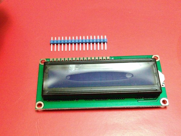
Step 3: 16X2 LCD Display
In this step, you can cut 2×6 pins and put them into the holes of the16x2 LCD Display in the corresponding pins: 1 to 6 & 11 to 16 so that you can have more space for working between the PCB and the Display when this last one be installed.
Step 4: 16X2 LCD Display 2
In this step, you are going to do the main connections to your display. Then, you should identify the connections from 16×2 LCD Display in the pins: 4, 6, 11, 12, 13, and 14 that will be connected later to Arduino Uno in the pins: 11, 9, 5, 4, 3, and 2 respectively without forgetting the connections to +5V, GND, and Pot of 10K.
Step 5: 16X2 LCD Display 3
In this step, you are going to match the connections done previously to your LCD Display with the future connections that you will do in the PCB: observe the photo where you can see the details closer.
Step 6: PCB
Once you know how to do the connections between your 16X2 LCD Display and the PCB, you should separate them so that you can install on the PCB: the Connector Unshrouded Headers by utilizing 2X8 pins in the side of the digital pins while using 2 pins in the other side for connecting to GND and +5V.
Read more: Arduino Digital Capacitance Meter