
Summary of Build the Internet for your friend
This article describes replicating a prop from "The IT Crowd" TV show, known as "The Internet." Originally powered by a 9V battery, the author rebuilt it as a rechargeable device. The project involves four main circuits: a battery charging module, a step-up power booster, a power regulator, and an LED flasher. The build features a red LED for status indication and uses a DC barrel connector for charging instead of a USB port, making it a humorous and elegant gift for fans of the show.
Parts used in The Internet Prop:
- Adafruit battery charging breakout
- Lithium Ion Polymer Battery
- JST cable
- Common Cathode RGB LED
- Plastic beveled LED holder
- 4-pin I2C cable
- DC barrel connector
- Hot glue
- Power booster with adjustable output voltage
- 28-turn potentiometer
- 5V regulator with 0.4V linear drop-out
Background
A few years ago, a co-worker turned me on to this TV program called “The IT Crowd”. The show revolves around a two-person IT team and their “Relationship Manager”, Jen, who inadvertently landed the job by including some basic PC skills on her resume. Moss and Roy resent her for getting the position both wanted, and will occasionally try to help expose Jen as a hopeless non-technical leader that has no business leading IT – in fact, Jen doesn’t even know what IT stands for!
In one episode, Jen wins employee of the year and must give a speech to the board of directors and company executives. Moss and Roy decide to “help” Jen by allowing her to use “The Internet” in her speech to impress the leaders.
As you have seen from the video clip, the device is a simple black box with one red LED in the top center just flashing on and off. It was so simple and so elegant, I decided to reproduce the device and gave it as a gift to my co-worker. The device quickly became a huge hit.
The device is completely useless, but I guarantee that if you haven’t seen the show, binge watch it and you will want to build one right away. It makes a great gift, even to the person who has never seen the show. Simply give them the box and point them to the clips. If you have not seen the show, it is available on Netflix and Amazon.
In this project, I’ll share here how I built the box. I originally built it using a 9-volt battery, but later decided to make it rechargeable.
Building the Device
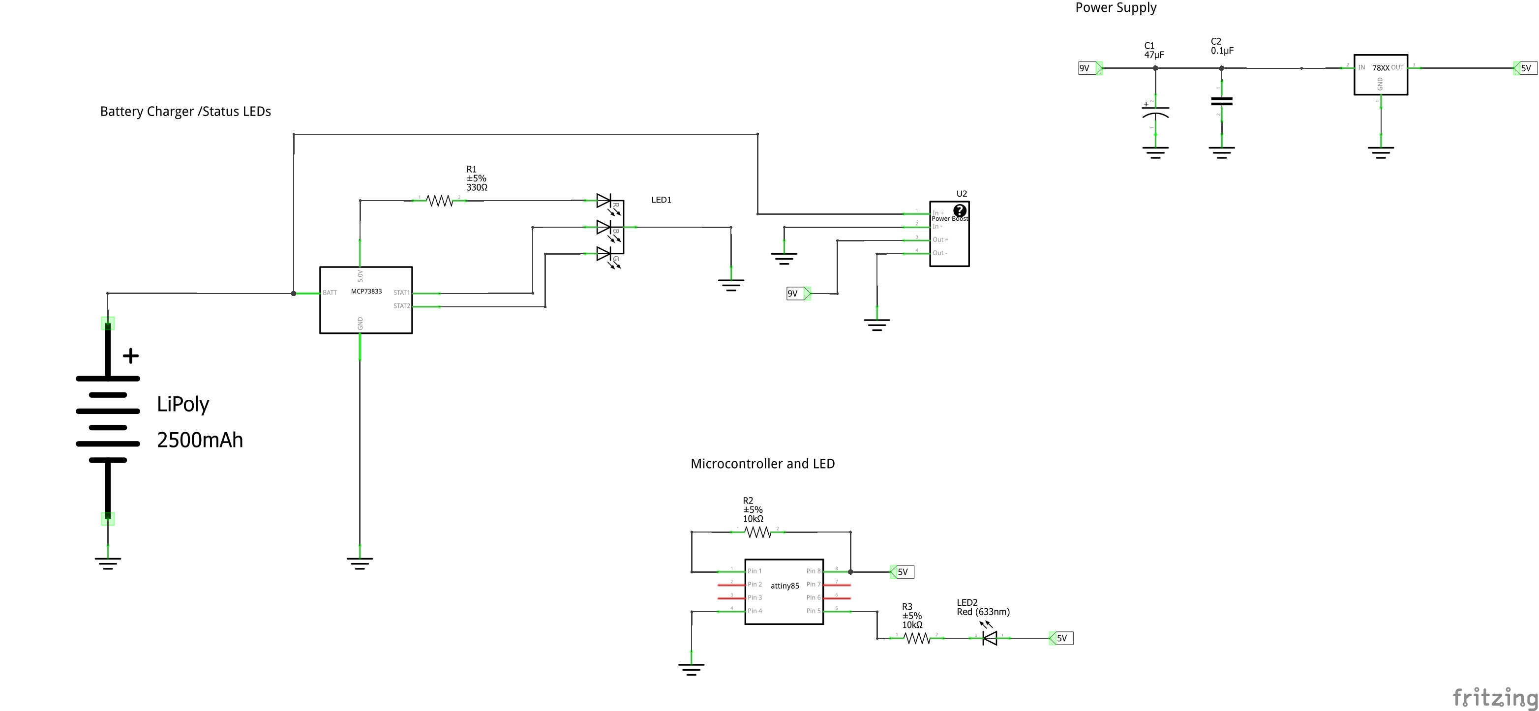
Although at first glance it may not seem like it, the device is fairly simple to build. It is comprised of several circuits combined. The first is the battery and charging circuit. The second is the step-up power booster. The third is the power regulator circuit and the final module is the LED flasher circuit.
Battery and Charging Module
If you purchase the battery charging breakout and the battery from Adafruit it includes the necessary JST cable to connect to the power booster module. The Common Cathode RGB LED is used to show the charging status outside of the box. I mounted the LED using a plastic beveled LED holder. Drill a hole in the side of the box to match the holder and clip the LED in. I used a lot of hot glue to keep the LED in place. Using the 4-pin I2C cable connect the header end over the four RGB LED pins and solder the other ends into the USB charger, The RED LED pin goes to the DC IN + pin. The next LED pin goes to Status Pin #2 and the last LED pin goes to Status Pin #1. The cathode pin of the LED is connected to ground.
This circuit can be tested by connecting the battery using the JST pin and plugging in a USB cable to the charger. When the battery is charging, the LED color will be orange. When charging is complete, the LED color will be purple.
Instead of trying to expose the USB port for charging, I soldered in a DC barrel connector. Connect the center pin of the DC barrel connecter to DC IN + and the outer pin to DC IN –. I connected a USB cable to the barrel connector with a voltage meter to verify the correct connections.
The DC barrel connector I used required a 1/2″ hole in the side of the box for mounting.
I used a hot glue to mount the battery inside the box. I mounted every part to the top portion of the box to make it easier to remove the bottom plate.
Power Booster
I use a power booster to take the 3.7 V from the Lithium Ion Polymer Battery to a voltage big enough for the 5V regulator. The regulator I chose has a 0.4V linear drop-out, so the voltage needs to be at least 5.4V. The booster I chose has an adjustable output voltage and uses a 28-turn potentiometer making it precisely tunable. I adjusted mine to 9V since I had previously been using a 9V battery to power the original box.
For more detail: Build the Internet for your friend
- What is the primary function of the device described?
The device is completely useless but serves as a humorous prop inspired by a TV show episode. - How can you tell if the battery is charging versus fully charged?
The LED turns orange when charging and purple when the charging is complete. - Can this device be recharged using a standard USB port?
No, the author soldered in a DC barrel connector instead of exposing a USB port for charging. - Why was a power booster necessary in the circuit design?
The booster takes the 3.7 V from the Lithium Ion Polymer Battery up to at least 5.4 V required by the regulator. - What specific component allows for precise tuning of the output voltage?
A 28-turn potentiometer on the power booster makes the output precisely tunable. - How did the author modify the original 9-volt battery setup?
The author converted the device to be rechargeable using a Lithium Ion Polymer Battery and added a charging circuit. - What color does the Common Cathode RGB LED display during the charging process?
The LED displays an orange color while the battery is charging. - How was the LED physically secured inside the box?
The LED was mounted using a plastic beveled LED holder and secured with a lot of hot glue.
