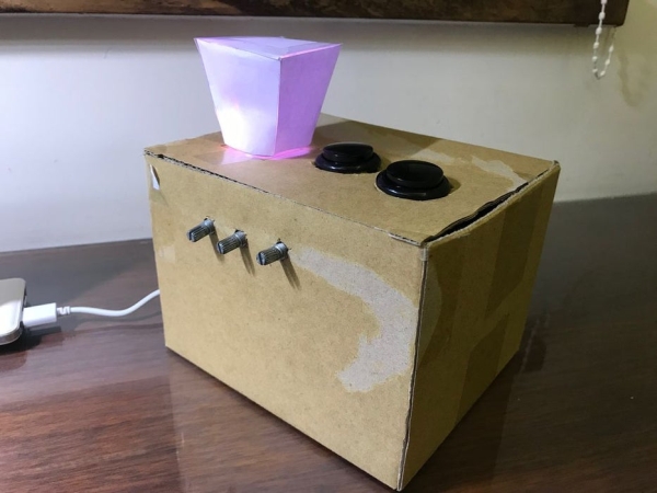
There’s a lot of night lamps outside, but they can’t customize to your favorite color. So, this project is to make a night lamp that you can choose your favorite color.
Step 1: Step One: Electronics Needed
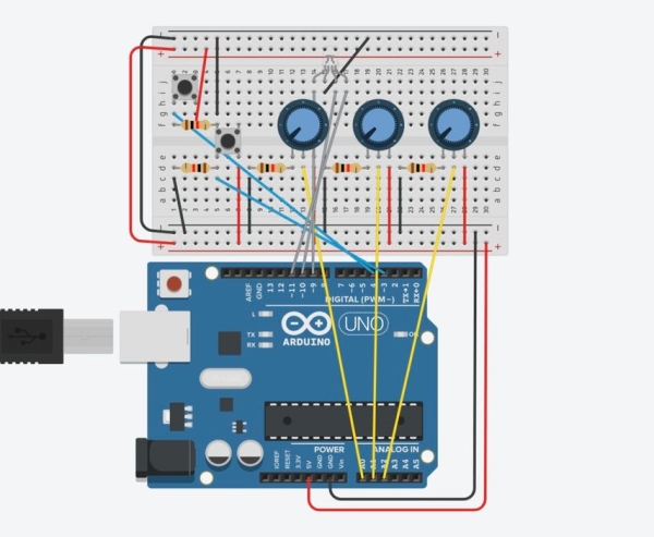
Here are the electronics you need to make the Decoration.
1. 2* Arduino buttons 6*6*5 mm Purchase here
2. 1* RGB LED 5mm Purchase here
3. Male to Male Breadboard Jumper Wire Purchase here
4. Male to Female Breadboard Jumper Wire Purchase here
5. Breadboard Purchase here
6. Arduino Leonardo Purchase here
7. USB to Micro USB Wire Purchase here
8. 1/4w Resistor 5% Purchase here
9. 1/4w Resistor 1% Purchase here
10. Potentiometer *3 Purchase here
Step 2: Step Two: Other Materials Needed

Paper box (I used a 16 * 14 * 11 cm box, but any box that is large enough to hold your Arduino and the circuits will be enough.
Tape
Knife
Pen or Pencil
Paper (A4)
Step 3: Step Three: Coding
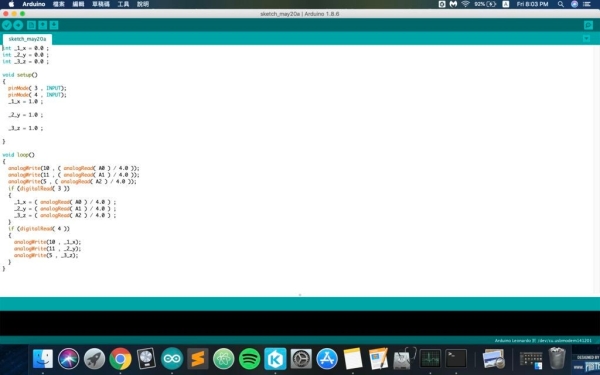
There are two parts of the code. One part of the code is from the potentiometer to the RGB LED. The code works like this, when the potentiometer sends the signal or a number to Arduino, Arduino will send it to the RGB LED, and one of the colors will glow. This is why we need three potentiometers. The second part is from the buttons to the RGB LED to the second button. When I press the first button, it saves the current situation on the RGB LED, and then when I press the second button, the RGB LED will be back to the previous situation saved in Arduino.
The code looks like this:
<p>int _1_x = 0.0 ;<br>int _2_y = 0.0 ;
int _3_z = 0.0 ;</p><p>void setup()
{
  pinMode( 3 , INPUT);
  pinMode( 4 , INPUT);
  _1_x = 1.0 ;</p><p>  _2_y = 1.0 ;</p><p>  _3_z = 1.0 ;</p><p>}</p><p>void loop()
{
  analogWrite(10 , ( analogRead( A0 ) / 4.0 ));
  analogWrite(11 , ( analogRead( A1 ) / 4.0 ));
  analogWrite(5 , ( analogRead( A2 ) / 4.0 ));
  if (digitalRead( 3 ))
  {
    _1_x = ( analogRead( A0 ) / 4.0 ) ;
    _2_y = ( analogRead( A1 ) / 4.0 ) ;
    _3_z = ( analogRead( A2 ) / 4.0 ) ;
  }
  if (digitalRead( 4 ))
  {
    analogWrite(10 , _1_x);
    analogWrite(11 , _2_y);
    analogWrite(5 , _3_z);
  }
}</p>
Step 4: Step Four: Assembling the Circuits
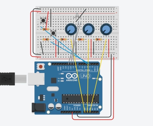
Now, it is time to assemble the circuits. The circuits are as shown at the top.
However, this is good before putting into the box. Once you’ve finished testing the circuits and check for mistakes, you should do a little more things before you put into the box.
Step 5: Step Five: Assembling the Circuits to Put Into the Box
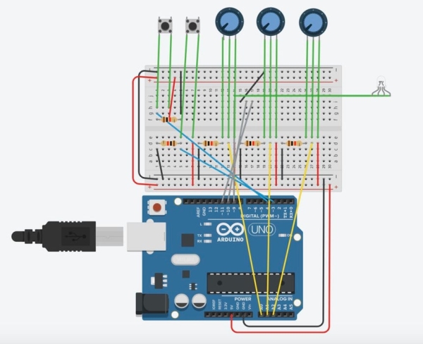
This step is fairly easy. Basically, just drag all of the inputs and outputs out with wires so we can put it on the box. Once you’re finished with that, the circuits are assembled and it can basically work.
Step 6: Step Six: Making This Box and Decoration
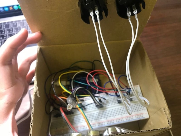
After you’ve assembled the circuits, you can start making your box. The main usage of the box is to cover your circuits, make your buttons, LED, and potentiometer from moving around, and decorate to make it look nicer. I’m using a 16*14*11 cm box, but any box that is big enough to hold your Arduino and circuits will be enough.
So, the procedure are as follows:
I put all of my circuits into the box. I cut the holes for my LED, buttons, and potentiometer. How I put them is the potentiometer on the side, and the buttons and LED on the top of the box. I tape the LED, buttons, and potentiometer on the box to make it stable. I cut a small hole on the side of the box so I can charge my Arduino when I want to use it. I make sure the circuits are connected correctly and that nothing falls off. Sometimes, the circuits aren’t stable enough, so it may fall off. By checking all the circuits, it prevents short circuits that may be dangerous.
Read more: Arduino Decoration
