Summary of Steam Linked Display Shelf
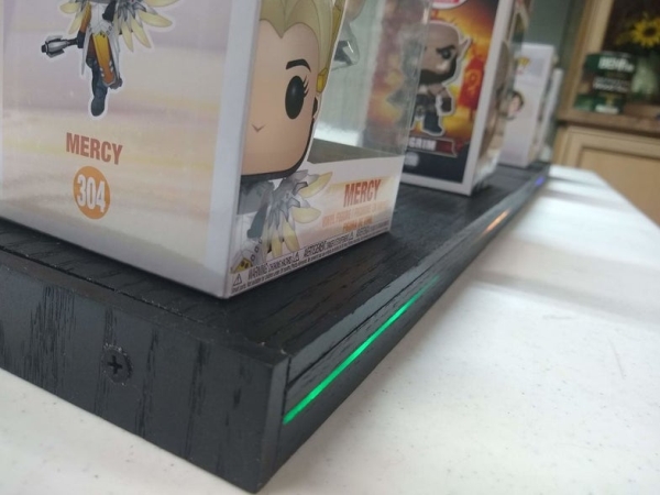
Summary: A custom LED display shelf shows Steam user statuses using an ESP8266 (NodeMCU), diffused LED strips, and woodworking to hold Funko POP figures. It features Wi-Fi setup, a dimmer potentiometer, low power use, and a single long shelf design; electronics are housed in a small project box with a DC jack and controls.
Parts used in the Steam Linked Display Shelf:
- NodeMCU V1.0 ESP8266
- USB 2.0 A-Male to Micro B Cable (for programming)
- 22 Gauge Silicone Wire 10ft
- 1/8 inch Expandable Braided Sleeving 10ft
- Panel Mount DC Jack
- 5V 2 Amp DC Power Supply
- Project Box
- Potentiometer (dimmer)
- Solder
- 22 AWG project wire
- LED Strip
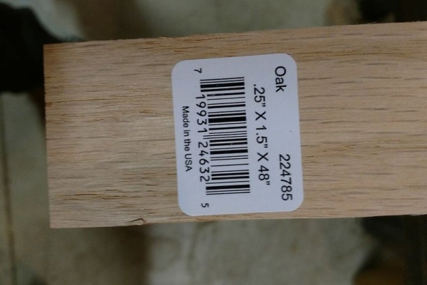
- Oak 0.25 x 1.5 x 48 board
- Oak 0.5 x 1.5 x 48 board
- Two Oak 0.25 x 5.5 x 48 boards
- Polycarbonate sheet 8 x 10
- Two-part epoxy
- Wood glue
- Magnets .315 Dia x .118 Thk (optional)
- Ebony stain (optional)
- Spray polyurethane (if stained)
- Painters tape
Back Story
My brother has Funko POP figures that represent his characters that his friends play most often in video games. We thought that it would be cool if they had a display case that would have LEDs in it to represent their status on Steam. So with my previous experience with Arduino, Steam API, and woodworking, I said that I could probably figure something out.
For anyone that does not know what Steam is, Steam is a digital distribution platform developed by Valve Corporation for purchasing and playing video games with a built-in communication system. Steam also has the ability to allow users to view what others are playing, if the person is on their computer, away, in game, etc, it even lets you play with them if you so choose.
Features / Design
Once we decided that we were going to make this project I sat down a started to write out some features that I knew that this would need to have.
- Wireless Wi-Fi setup/login like a Chromecast.
- Dimmer / on-off switch.
- Defused LEDs.
- Status LED modes.
- Zero upkeep after setup and build.
- POP figurines must sit on/in.
- Must not be power hungry.
After deciding what the project needed to include me and my brother started to go over designs until we got what we have now.
An Important Note
The original design was a box with multiple levels. However, once we had built the two bases we thought that it would look better as one long shelf instead of a box with multiple levels. I am going to try my best to explain how we would have built it if we had started with the new design, so if you notice in some of the pictures that we have slightly different sized pieces this is the reason.
Step 1: Materials
Electronics
- NodeMCU V1.0 ESP8266 (Link)
- USB 2.0 A-Male to Micro B Cable (For programming)
- 22 Gauge Silicone Wire 10ft (Link)
- 1/8 inch Expandable Braided Sleeving 10ft (Link)
- Panel Mount DC Jack (Link)
- 5V 2 Amp DC Power Supply (Link)
- Project Box (Link)
- Potentiometer (Link)
- Solder (Just about any electrical solder will work)
- 22 AWG project wire (Link)
- LED Strip (Link)
Project Wood (Home Depot See Pictures)
- 1 Oak .25″ X 1.5″ X 48″
- 1 Oak .5″ X 1.5″ X 48″
- 2 Oak .25″ X 5.5″ X 48″
- 1 Polycarbonate sheet 8″ X 10″
Note that a .5″ X 5.5″ X 48″ board is shown in the pictures but is not used in the project.
Assembly
2 Tubes of two-part epoxy (Home Depot)Wood Glue (Home Depot)Magnets .315″ Dia X .118″ Thk (Home Depot) (Optional)Ebony stain (Home Depot) (Optional)Spray Polyurethane (If stained)Painters tape
Step 2: Tools
These are the tools that we used.
- Table Saw
- Radial Arm Saw
- Clamps
- Belt Sander
- Bandsaw
- Hot glue gun
- Scissors
- Soldering iron
- Wire stripper
- Power drill
- Drill press
- Sand Paper
- Tape measure
- File
Although we used these tools it does not mean that you have to use these exact tools. It would only help step by step if you are looking to directly replicate the project. For example, the bandsaw could be substituted for a jigsaw, a scroll saw, a hand saw, etc.
Step 3: Building the Project Box
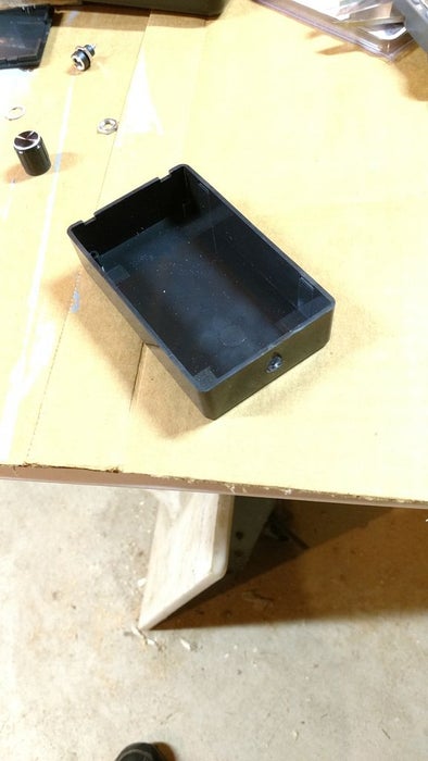
- First, drill a hole in the project box from whatever side you would like to be the front, this will be for the dimming potentiometer. We drilled this hole on the small side right in the middle. If you are using the potentiometer listed in the parts list the best drill we found to use for this was 17/64 (Picture 1).
- Secondly, drill a hole in the back for the wires that will be going to the shelf, when looking at the box from the front we put this hole in the back left, we found that 3/16 drill worked best for this but it was a tight fit.
- Next, drill a hole in the back for our dc power jack, we put this on the back right side. If you are using the power jack in the parts list the best drill for this was a 5/16. (Picture 2)
- After that, drill a hole in the back for the reset button (this exact button is not listed because we got it out of our Arduino box) we put this right next to the power jack.
- Before assembling the project box we filed off the tab on the potentiometer as we can tighten the potentiometer tight enough so we don’t actually need it.
- Finally, put all of the parts in their respective holes and tighten them down. (Picture 3)
Read more: Steam Linked Display Shelf
- What microcontroller is used in the project?
The project uses a NodeMCU V1.0 ESP8266. - How is the device powered?
It is powered via a 5V 2 Amp DC power supply connected through a panel mount DC jack. - Can the LED brightness be adjusted?
Yes, a potentiometer is installed in the project box to act as a dimmer. - How are the LEDs mounted or diffused?
The design uses LED strip with a polycarbonate sheet to diffuse the LEDs. - Does the project support wireless setup?
Yes, it includes wireless Wi-Fi setup and login like a Chromecast. - What woodworking materials are required?
Various oak boards (specified sizes) and an 8 x 10 polycarbonate sheet are used for the shelf and diffuser. - Are magnets required for assembly?
Magnets (.315 Dia x .118 Thk) are listed as optional parts for assembly. - Is special solder required?
No, the article states just about any electrical solder will work. - Where is the potentiometer mounted?
The potentiometer is mounted in a drilled hole on the front small side of the project box. - What tools are recommended for building the shelf?
Tools used include table saw, radial arm saw, clamps, belt sander, bandsaw, hot glue gun, soldering iron, drill, drill press, and sandpaper, though alternatives can be used.