
Summary of Arduino and CueCat barcode scanner
The article details how to repurpose a 10-year-old CueCat barcode scanner with an Arduino. The author bypasses the device's encryption by intercepting raw PS2 signals via hardware modification and software decoding. The setup involves cutting the original Y-cable to access specific data lines, connecting them to an Arduino terminal shield using interrupt-capable pins, and utilizing the PS2 library to translate encrypted keystrokes into readable ASCII codes for serial output.
Parts used in the CueCat Barcode Scanner Project:
- CueCat barcode scanner
- Arduino board (specifically Mega 2560 mentioned)
- PS2 keyboard library for Arduino
- Terminal shield
- Soldering iron and flux
- Multimeter for continuity testing
- Terminal emulator software (TeraTerm, Putty, or SecureCRT)
– unencrypt the barcode in software on the arduino
– i didn’t want to cut into the Cuecat in case I broke it, not hard to replace, but that’s not the point 😉
– get it to write only the bar code to the serial port, and I can use some terminal emulator (TeraTerm,Putty or SecureCRT) to write the data to a file as I furiously scan like a boss all items with a barcode in the house.
Step 1: Connecting the CueCat to Arduino
There is no continuous path between the 2 ports (Except Power and GND) as a multimeter and continuity test confirmed. So using the female port as a way to access the cuecat signal did not work.
PS2 female connectors are hard to find these days, so I cut the female connector from the cuecat and used that to break out the wires…
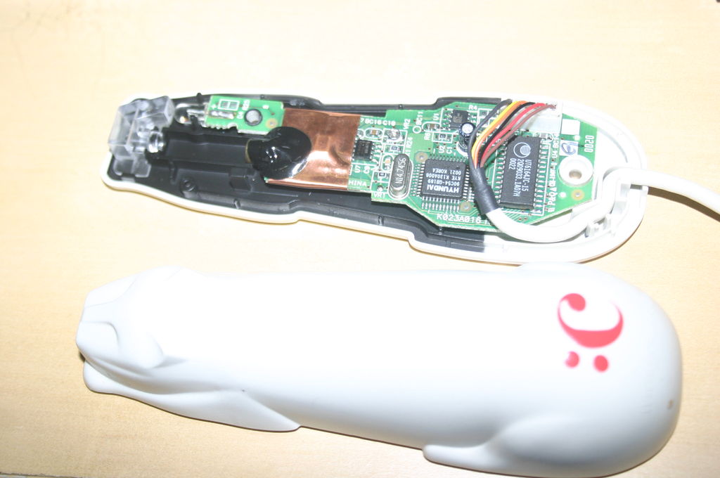
The Cue cat cable has 6 wires, marked on the board as 1-6
1. Brown (+5V)
2. Red (DATA Female connector)
3. Black (Clock Female Connector)
4. Orange (DATA Male connector)
5. Yellow (Clock Male Connector)
6. Black – Cable is thicker than other black (Ground)
When cut, the female adapter, has the following which will map to the connector inside the Cuecat as follows
1. Brown (+5V)
2. Red (DATA Female connector) to Orange(pin4)
3. Black (Clock Female Connector) to Yellow (pin5)
4. Bare wire (GND)
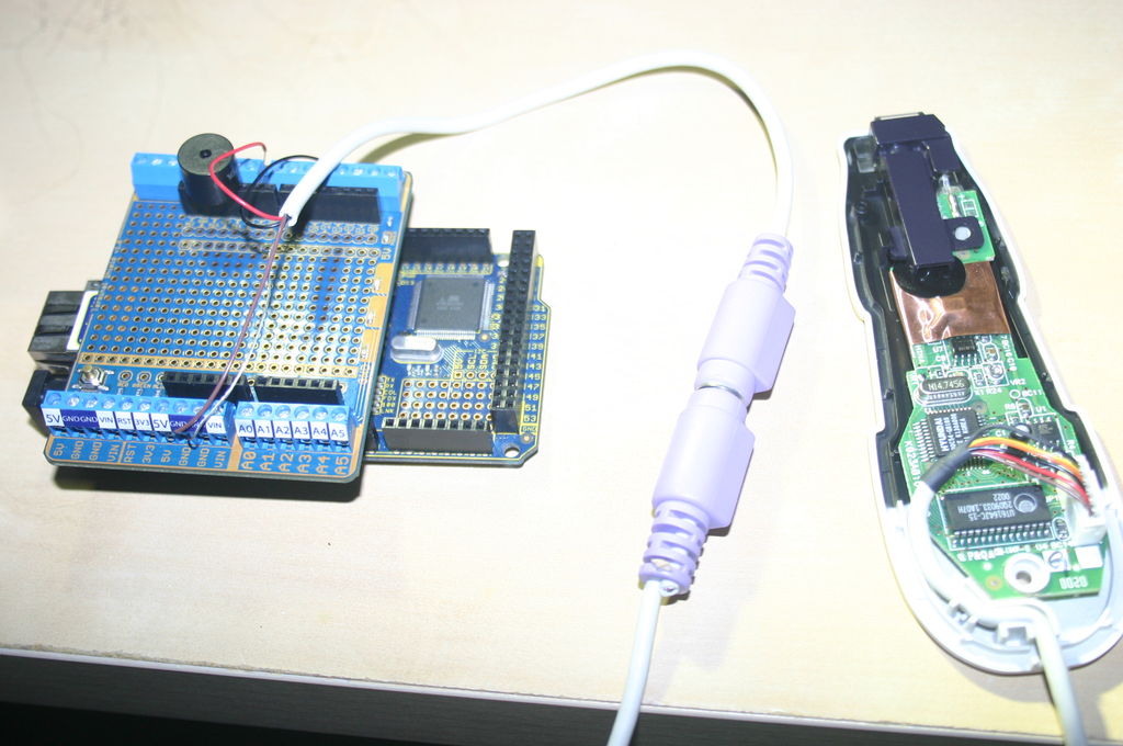
I tinned the wires with flux and solder to make them a little more durable, and wired them to a terminal shield on the Arduino.
Step 2: Getting the first code
http://www.arduino.cc/playground/Main/PS2Keyboard
The only thing to watch out for is;
– The CLK is used as interrupt, and so ensure you connect to a pin that supports interrupts
e.g. on the Mega 2560 http://arduino.cc/en/Main/ArduinoBoardMega2560
External Interrupts: 2 (interrupt 0), 3 (interrupt 1), 18 (interrupt 5), 19 (interrupt 4), 20 (interrupt 3), and 21 (interrupt 2).
I used Pin 3… Which is a bit annoying as now all the pins are not on same side of the board 🙁 (first world problems)
And a few swipes, check all wires are connected right and …
.C3nZC3nZC3nYCNP1Chz6CNnY.bNjW.D3T6C3nZE3jZD3bZDa.
TIP: Look at ASCII codes, NOT printable characters…
You can see I played with the code a little, as when looking at output there are always non printable characters, so I wrote the code to show the ASCII code.
Useful: http://en.wikipedia.org/wiki/ASCII
OUTPUT ASCII value -> printed Character
International Keyboard Test:
46->.
67->C
51->3
110->n
89->Y
[deleted for brevity…]
88->X
69->E
87->W
46->.
13->
Note that there does not seem to be anything strange at the start, but the end is /13 which is a Carriage return, ie, end of the code
I did expect to see ALT-F10 being sent as on my linux box it kept minimising and expanding the window on each scan, and that is the keystroke that does that… if the Arduino doesn’t see it, then I am OK with that…
 cuecat_input-120709a.zip
- How does the CueCat connect to the Arduino?
The device connects by modifying its Y-cable to access internal wires and wiring them to a terminal shield on the Arduino. - Can I use the female port of the original cable to access signals?
No, a continuity test confirmed there is no continuous path between the two ports except for Power and GND. - Which Arduino pins support interrupts for this project?
Pins that support interrupts include 2, 3, 18, 19, 20, and 21 on the Mega 2560 board. - What happens if I look at printable characters instead of ASCII codes?
You will see non-printable characters; the author advises looking at ASCII values to correctly interpret the data. - How do I know when a barcode scan ends?
The end of the code is marked by a Carriage return character, which has an ASCII value of 13. - Why did the author cut the female connector from the CueCat cable?
PS2 female connectors are hard to find, so cutting the existing one allowed access to the necessary wires. - What software can be used to write scanned data to a file?
Terminal emulators like TeraTerm, Putty, or SecureCRT can be used to write data to a file while scanning. - Does the Arduino receive the ALT-F10 keystroke mentioned?
The author notes they did not expect to see this keystroke and were okay if the Arduino did not see it either.
