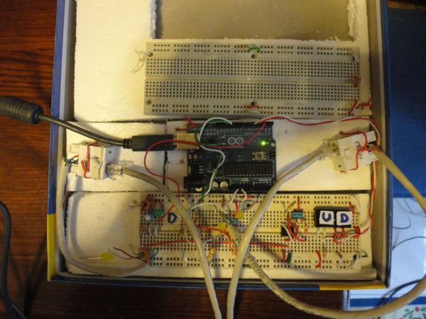
In this introduction I will show you a overview of this project whit Arduino Uno. The purpose of this instructable is move a electric roller shutter by Arduino Uno. The prototype that I made is my first electronic project with Arduino and I hope this instructable and the solutions that I found are useful for your own Arduino’s and electronics projects. My aim was to transform a simple electric roller shutter in a domotic roller shutter; also, a possible development, could be a complex domotic system for a house: a central microcontroller (another Arduino) that control all electric roller shutters connected to it whit the possibility to create for example some scenes. This project is limited only to realize a prototype and after so many years I wanted to return to build electronic circuits.
Features:
– Move the roller shutter when push the button
– Stop the roller shutter when it is completely open or closed
– Stop the roller shutter when push the button up while it’s moving down
– Stop the roller shutter when push the button down while it’s moving up
Operation principle
Arduino counts the holes on the roller shutter with the infrared receiver; the infrared diode is positioned on the other side of the roller shutter. When the hole is aligned with them, Arduino increment or decrement a counter to determinate the position of the roller shutter. To connect the actuators and the sensor to Arduino I used two LAN cables (see last step)
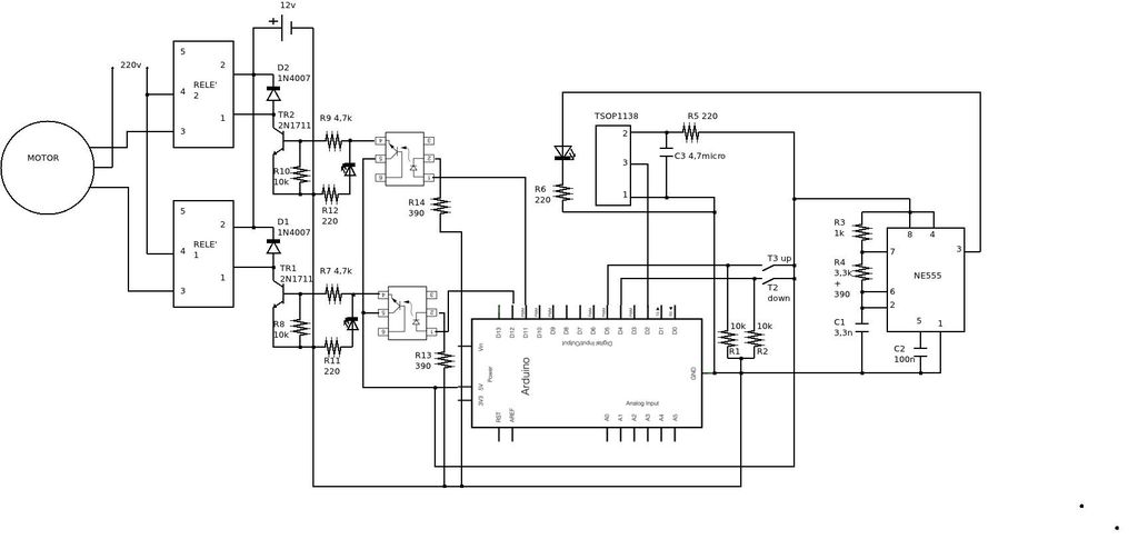
Step 1: Scheme
 Scheme.zip98 KB
Step 2: Software
I hope comments are exhaustive:
// costants:
const int sm = 2; // moviment sensor
const int buttonPin_t3 = 5; // button up
const int buttonPin_t2 = 4; // button down
const int ledPin = 13; // LED for check buttons
const int d1 = 11; // motor UP
const int d0 = 12; // motor DOWN
// variables
int ContatoreSensoreMovimento = 0; // counter move sensor
int Contatore_t3_t2 = 0;
int RegistroOutputd1 = 0;
int RegistroOutputd0 = 0;
For more detail: Domotic Arduino