Summary of Arduino controls cheap RC car transmitter
This article details a project to control a cheap Chinese RC car's transmitter using an Arduino Uno. By interfacing the Arduino with the TX2/RX2 IC-based remote, users can automate steering functions without manual joystick input. The guide emphasizes scavenging parts due to high component costs in certain regions and provides step-by-step instructions for disassembling the car, wiring the transmitter to the microcontroller, and testing the system.
Parts used in the Arduino Controlled RC Car:
- Arduino Uno or clone
- TX2 encoder IC
- RX2 decoder IC
- 2 X 10K Ohm resistors
- 2 X breadboards
- Wires and alligator clips
- 4 X AA batteries (6V source)
- DC motors
- H-bridge circuit components
OBJECTIVE
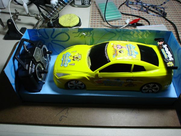
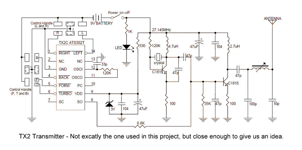
Cheap Chinese RC toy cars can be had for about 5 Euros in the local market. The wireless brains behind the majority of these cheap RC toys is a pair of very cheap ICs the TX2 and the RX2. Yup, that’s what they are called. So this tutorial is focused on the TX2/RX2 based remote controlled toys.
I bought one RC toy car a while ago and used the Arduino with an IR sensor to drive it. Then I figured why not use the Arduino to drive the radio control mechanism of the car. You can see a video of the steps involved and the final operational circuit here:
WHY?
I mentioned in my other projects how hard it is for most people in Jordan to afford buying electronic components because of the very low income, absurdly high tariffs (mostly to feed rampant government corruption), and arbitrary security procedures. So scavenging parts from cheap gadgets is the way for most young makers I know to sustain their passion for electronic innovation.
CREDITS
Special thanks to Eng. Jafar Quttaineh for his invaluable assistance.
FEEDBACK
Your feedback is most welcome to help me improve my future projects.
Let’s get started…
Step 1: Getting started
APPROACH
In this project, I will use the Arduino to drive the transmitter’s LEFT and RIGHT functions. So instead of the user pushing the remote control’s joystick to turn the car (or my test rig) , the Arduino can be connected and programmed instead to send these commands via the RC car’s transmitter. The same steps can be duplicated to enable the Arduino to drive the transmitter’s BACK and FORWARD function pins.
I extracted both receiver and controller circuits from the RC car but you may find it easier to just work with the transmitter + Arduino while leaving the receiver and the car intact. This might be simpler for some of you since you have to only worry about dissecting and wiring the transmitter to the Arduino. Also, the intact receiver + car will act as your test platform. It’s also more fun to end your project with your Arduino controlling your RC car instead of just looking at two naked circuits and a blinking LED. Your call.
COMPONENTS
The car has three main components.
1) Mechanical: For steering and locomotion, the car has 2 DC motors and associated gear. One motor provides locomotion from the back of the car, the other DC motor in the front provides steering left and right. I won’t be using the motors in this project but these toy cars are a great source of motors, gears, h-bridges, and other parts. So I am not throwing anything away.
2) Electronic: There are three main circuits. a) the transmitter b) the receiver c) the H-bridge. The transmitter and receiver are driven by the venerable TX2 encoder and RX2 decoder ICs. The h-bridge to drive the DC motors uses power transistors. Refer to the datasheet for more details.
3) Power: The transmitter is powered by 2 AA batteries (3V) and the receiver/car comobo is powered by 4 AA batteries (6V).
PARTS NEEDED FOR THIS PROJECT
– Arduino Uno or clone.
– 2 X 10K Ohm resistors. I use each in a series to connect the transmitter’s pin to the Arduino’s digital pin. If you want to connect all steering functions (Left, Right, Back, Front) to the Arduino you will need 4 of those. 10K might be overkill but the circuit works.
– 2 X breadboards to place the transmitter and receiver for wiring. It just makes for easier handling and wiring. But you can do without the breadboard.
– Wires and alligator clips.
– 4 X AA (6V) battery source to supply the receiver.
– Multimeter to test your connections.
– DC motors, small DC lamps, or relays to test your final TX2/RX2 system depending on what you plan to use it for.
OPTIONAL LED TESTBED
I know some of you will be tempted to just use LEDs to test the rig. LEDs are nice and cheap and accessible. Since the receiver’s h-bridge (geek term for circuit that drives motors) switches between positive and negative voltage depending on whether it’s driving the motor in one direction or the other (e.g. Forward vs Back), we can’t just use LEDs as-is since an LED passes current in one direction only but not the other. But if you insist on using LED’s , I came up with a quick and dirty test circuit based on LEDs. I won’t describe it in detail because it’s not relevant to his project.
My LED testing circuit was put together on the fly. It’s a mini breadboard made up of two LEDs, two diodes, and two resistors both in parallel but rigged for opposite polarities. When the voltage is positive, one LED will turn on, when it’s negative, the other LED will turn on.
This is to simulate a motor turning one way (e.g. Right) or the other (e.g. Left). You don’t need to do this test circuit. Just connect a small DC lamp or a DC motor to test your circuit. I am sure there are better ways of doing this but it was the quickest at the time. I might add two more LEDs to simulate the 2nd motor’s Forward and Backward functions.
WORKING WITH DIFFERENT RC GADGETS
There’s a good chance your RX2/TX2 based RC gadget was made by a different vendor with different wire colors and based on different schematics. You should be able to apply the techniques from this project to other RX2/TX2 based RC projects with a modest effort.
Step 2: Taking the RC car apart and re-wiring it with the Arduino
THE SHOWDOWN
And now for the fun part. Putting the pieces together to give Arduino control over the transmitter.
For the purposes of this project, I am only connecting the Arduino to the Right/Left function pins of the TX2, pins 1 and 14. But the process is very similar to connect Arduino to the Forward and Back pins 5 and 4.
Keep the antenna connected to the receiver for better results. In a production environment, attach the original antennas back on the receiver and transmitter, to squeeze in every extra feet of transmission range.
The receiver circuit is also integrated with an h-bridge circuit used to drive the 2 motors. The yellow, green, and blue cables supply positive or negative voltage to spin the motor clockwise or counterclockwise. The RX2 receiver decides, based on the transmitter function signal, which DC motor spins and in what direction. In the final production, you can use the h-bridge output to drive relays or wheels, etc.
– 2 X 10K Ohm resistors
– 2 X breadboards
For more detail: Arduino controls cheap RC car transmitter
- What is the main objective of this project?
The goal is to use an Arduino to drive the transmitter's LEFT and RIGHT functions instead of a user pushing a joystick. - Why are cheap Chinese RC toys recommended for this project?
They contain very cheap TX2 and RX2 ICs, making them accessible for makers who cannot afford expensive electronic components. - Can I connect the Arduino to other functions besides Left and Right?
Yes, the same steps can be duplicated to enable the Arduino to drive the BACK and FORWARD function pins. - How many 10K Ohm resistors are needed if connecting all four steering functions?
You will need 4 of those resistors if you want to connect all steering functions including Front and Back. - Is it necessary to dissect both the receiver and controller circuits?
No, it is easier to work with just the transmitter and Arduino while leaving the receiver and car intact as a test platform. - Can LEDs be used directly to test the H-bridge output?
No, LEDs pass current in one direction only, so they cannot simulate the motor switching between positive and negative voltage without a specific parallel circuit. - Does the antenna need to remain connected during the project?
Yes, keeping the antenna connected to the receiver ensures better results and transmission range. - What powers the transmitter in this setup?
The transmitter is powered by 2 AA batteries providing 3V.