Summary of Arduino Controlled LEGO RC Tank and Transmitter
This article details the construction of a remote-controlled Lego tank integrated with Arduino and mechatronics. The project features a custom chassis, dual geared DC motors, and an NRF24L01 wireless communication system for stable control via a dedicated transmitter rather than Bluetooth. The author provides step-by-step instructions for mechanical assembly, including motor mounting and power management using a 5V power bank and AA batteries, alongside complete Arduino code for both the receiver (tank) and transmitter to handle directional movement and signal loss safety protocols.
Parts used in the Arduino Controlled LEGO RC Tank:
- Lego bricks and tracks
- 2x Geared DC motors (6v)
- 5v portable power supply (Power Bank)
- Arduino Uno or Nano
- L9110s motor driver
- NRF24L01 Remote Transceiver
- Breadboard
- Jumper Wires
- 10uf capacitor
- Copper clad board
- 2x Joysticks
- Toggle switch
- AA battery pack
- Hot glue and super glue
- Lego rod connector
I recently got my childhood Lego out and wanted to find a project that I could combine with Arduino and mechatronics. I started off building a digger but then realised a tank would be better because, well tanks are cool!
I originally built it to be controlled over Bluetooth from my phone but then wanted to take it further and make a remote transmitter to make the connection more stable.
Supplies
Receiver (tank) end:
A bunch of Lego including tracks
2x geared DC motors 6v
5v portable power supply
Arduino Uno or Nano
L9110s motor driver
NRF24L01 Remote Transceiver
Breadboard
Jumper Wires
10uf capacitor
Transmitter end:
Copper clad board or breadboard
2x joysticks
Arduino nano (Uno would work)
NRF24L01 Remote Transceiver
10uf capacitor
Toggle switch
Step 1: Chassis Construction
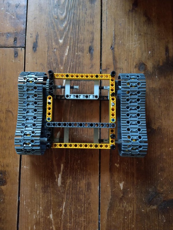
Here are photos of the chassis that I constructed. It doesn’t have to be the exact same as this but there does need to be a gear on each track side on the back. And don’t make the same mistake as me and ensure that each axle is independent as the tracks are responsible for the steering!
Step 2: Attaching the Motors
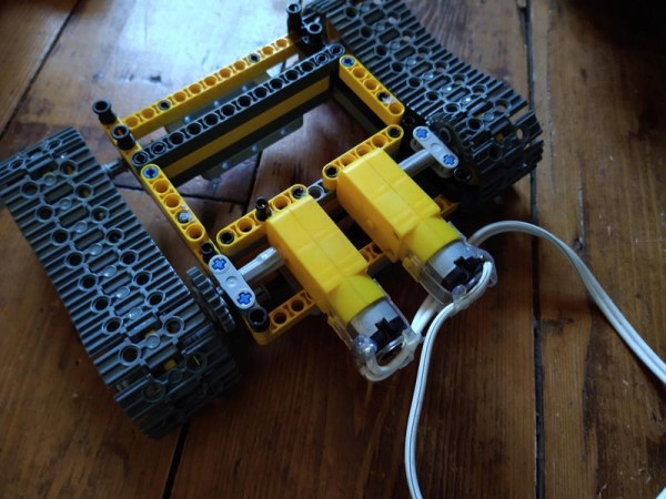
The motors that I got off eBay were double sided so I had to sand down one side in order to fit them in the chassis.
In order to ‘Legoise’ the motors I needed to heat up a Lego rod connector and slide it onto the motor shaft. The motor shaft is shaped so I didn’t have to worry about it slipping but did super glue it to avoid it falling off.
To attach the motors onto the Lego I hot glued the motor casing onto a beam piece as can be seen in the photo. This has proven to be a secure fixing so far. Finally attach a gear onto the motor shaft so that it meshes with the gear on the tracks.
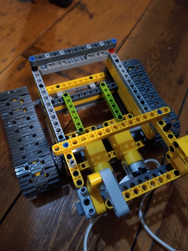
Step 3: Attaching Power Bank
I originally used AAs to power the tank and Arduino but found that they drained pretty fast! I realised that my power bank was 5v which turned out to be enough to power the motors. I did however use a separate pack of AAs to power the Arduino as I found when the motors were under load the current they drew was causing the Arduino to reset despite wiring the motors directly to the power supply.
In order to hold the power bank I assembled a Lego frame to fit on top of the chassis and has a detachable beam as a door to hold it in.
Step 4: Attaching Tray for Arduino
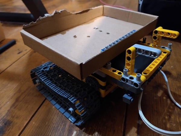
This photo shows a box that I attached to the top of the tank to hold the Arduino and components, I will eventually build a more permanent solution to this but as it is still an ‘ongoing’ project, I decided to keep the Arduino easily accessible.
Step 5: Coding the Arduino Receiver
Here is the receiver code for the Arduino and a link to download the required library from here.
//coded by jackofalltrails
//Remote control tank

// Include libraries
#include <SPI.h>
#include <nRF24L01.h>
#include <RF24.h>

// Setup pins (use 9 and 10 for uno or nano)
RF24 radio(9, 10);
const byte address[6] = "00001";

unsigned long lastReceiveTime = 0;
unsigned long currentTime = 0;

// Set a structure to hold all the data
struct Data_Package {
  byte leftstickx;
  byte leftsticky;
  byte leftstickbutton;
  byte rightstickx;
  byte rightsticky;
  byte rightstickbutton;
};

Data_Package data;

const int lefta = 5;
const int leftb = 6;
const int righta = 3;
const int rightb = 7;
int speedleft = 0;
int speedright = 0;

void setup()
{
  radio.begin();
  radio.openReadingPipe(0, address);
  radio.setAutoAck(false);
  radio.setDataRate(RF24_250KBPS);
  radio.setPALevel(RF24_PA_LOW);
  radio.startListening(); //  Set the module as receiver
  resetData();

  // TODO you setup code
  pinMode(lefta, OUTPUT);
  pinMode(leftb, OUTPUT);
  pinMode(righta, OUTPUT);
  pinMode(rightb, OUTPUT);
}

void loop()
{
  if (radio.available()) {
    radio.read(&data, sizeof(Data_Package)); // Reads the data and stores it in the defined structure
    lastReceiveTime = millis();
  }
  currentTime = millis();
  if ( currentTime - lastReceiveTime > 1000 ) { // If the time is more than 1 second then the signal has been lost
    resetData(); // If connection is lost, reset the data to avoid the tank driving off!
  }
  int lefttrackcontrol = data.leftsticky;
  int righttrackcontrol = data.rightsticky;

  if (lefttrackcontrol > 137){
    speedleft = map(lefttrackcontrol, 0, 127, 10, 255);
    analogWrite(lefta, speedleft);
    analogWrite(leftb, 0);
  }
  else if ((lefttrackcontrol >= 117) and (lefttrackcontrol <= 137)){
    analogWrite(lefta, 0);
    analogWrite(leftb, 0);
  }
  else if (lefttrackcontrol < 117){
    speedleft = map(lefttrackcontrol, 0, 127, 255, 10);
    analogWrite(lefta, 0);
    analogWrite(leftb, speedleft);
  }

  if (righttrackcontrol > 137){
    speedright = map(righttrackcontrol, 0, 127, 10, 255);
    analogWrite(righta, 0);
    analogWrite(rightb, speedright);
  }
  else if ((righttrackcontrol >= 117) and (righttrackcontrol <= 137)){
    analogWrite(righta, 0);
    analogWrite(rightb, 0);
  }
  else if (righttrackcontrol < 117){
    speedright = map(righttrackcontrol, 0, 127, 255, 10);
    analogWrite(righta, speedright);
    analogWrite(rightb, 0);
  }
}
void resetData() {
  // Reset the values when there is no radio connection to avoid the tank wandering off into the distance!
  data.leftstickx = 127;
  data.leftsticky = 127;
  data.rightstickx = 127;
  data.rightsticky = 127;
  data.leftstickbutton = 1;
  data.rightstickbutton = 1;
}
It starts off by including the libraries as in all Arduino codes.
It then sets up the radio connection using pins 9 and 10 which are the ones to use on Arduino Uno and Nano boards. A data packet is then set up to hold all the variables to be received from the transmitter.
The variables for outputs are then set and the radio connection is started.
The code then seeks to find a receiver to gain data from and if it cant find it then it links to the resetData() loop to reset all the inputs to neutral to avoid the tank continuing to drive when connection is lost!
Lines 62 to 93 controls the movement of the tank. Firstly each track variable is set to the input from the stick data received from the transmitter. Then it determines if the lefttrackcontrol (which is the data from the leftsticky) is bigger than 137 and if so then it maps the speed of the left track to half of the stick input as it is going to be moving from middle to top to go forward. It maps this to 10 – 255 which is the range in which the motor controller works off (by starting at 10 it removes the buzzing from the motors). It then writes this to the outputs connected to the motor controller.
Lines 70 – 72 ensure that when the stick is in the middle then the tank doesn’t move. I had to do some trial and error on the numbers 117 and 137 to ensure that there was some room for the tolerances on the pots on the sticks.
It then repeats this for driving the track backwards and for the right track.
Step 6: Wiring the Tank
Connect the wires as shown in the diagram above.
It may look complicated and confusing but it is relatively simple to construct. The 10uf capacitor is connected across the 3v3 and ground pin on the NRF24L01 to keep the voltage more stable and therefore the receiving of the radio. Ensure that this capacitor is the correct way around as they ARE directional.
The motors are wired as the left one is b and the right is a. The polarity of the motors is often unknown so just wire them in as shown and then they can be swapped around if needed. The only thing that will happen if they are around the wrong way is forward will be backwards and vice versa.
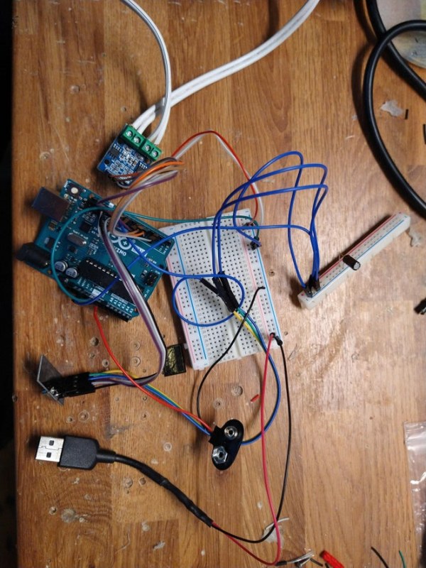
Step 7: Assemble Remote Transmitter Circuit
Assemble the remote transmitter circuit as can be seen in the diagram above. Use a 10uf capacitor again across the 3v3 and ground to ensure a stable connection. Please note that the wiring of the sticks varies depending on the model but will be the very similar for different models.
Assemble the remote transmitter circuit as can be seen in the diagram above. Use a 10uf capacitor again across the 3v3 and ground to ensure a stable connection. Please note that the wiring of the sticks varies depending on the model but will be the very similar for different models.
I first assembled the circuit on a breadboard, checked it worked, and then soldered it onto a copper clad board to make it secure and permanent. In order to mount the sticks to the copper board so that they were flat against it, I had to first solder a pin header to the copper clad and then solder the stick pins to that (this can be seen in the image above). A switch can be added onto the live of the battery to enable the controller to be turned off.
Source: Arduino Controlled LEGO RC Tank and Transmitter
-
Why did the author switch from Bluetooth to a remote transmitter?
The author switched to a remote transmitter to make the connection more stable. -
How should the axles be configured on the Lego tank chassis?
Each axle must be independent because the tracks are responsible for steering. -
What power sources were used for the motors and the Arduino?
A 5v power bank was used for the motors, while a separate pack of AAs powered the Arduino. -
Why is a 10uf capacitor necessary in the circuit?
The capacitor is connected across the 3v3 and ground pins on the NRF24L01 to keep the voltage stable for receiving radio signals. -
What happens if the radio signal is lost during operation?
The code resets all inputs to neutral after one second of no signal to prevent the tank from driving off. -
How are the motors attached to the Lego chassis?
Motors are secured by hot gluing the casing to a beam piece and attaching a gear to the shaft that meshes with the track gears. -
What pin numbers are recommended for the RF24 library on Arduino Uno or Nano?
Pins 9 and 10 should be used for the radio connection on Arduino Uno or Nano boards.