
Summary of Arduino Color Mixing Lamp using RGB LED and LDR
This Arduino project builds an automatic color-mixing lamp that changes its RGB LED color based on ambient light. Three LDRs detect light levels for red, green, and blue channels; the Arduino varies PWM duty cycles to adjust each channel’s intensity, producing different colors. The lamp uses a Common Anode RGB LED and appropriate resistors and colored strips to enhance corner lighting.
Parts used in the Arduino Color Mixing Lamp:
- Arduino UNO
- Breadboard
- 3 × 220-ohm resistors
- 3 × 1-kilohm resistors
- Jumper wires
- 3 × LDRs (photoresistors)
- 3 × colored strips (red, green, blue)
- 1 × RGB LED (Common Anode)
What if we can generate different colors using a single RGB led and make our room’s corner more attractive? So, here is a simple Arduino based color mixing lamp which can change color when there is change in light in the room. So this lamp will automatically will changes its color according to the light conditions in the room.
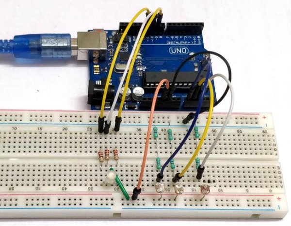
Every color is the combination of Red, Green and Blue color. So we can generate any color by using red, green and blue colors .So, here we will vary PWM i.e. intensity of light on LDRs. That will further changes the intensity of red, green and blue color in RGB LED, and different colors will be produced.
Below table shows the color combinations with respective change in duty cycles.
Materials required:
- 1 x Arduino UNO
- 1 x Breadboard
- 3 x 220-ohm resistors
- 3 x 1-kilohm resistors
- Jumper wires
- 3 x LDRs
- 3 x colored strips (red, green, blue)
- 1 x RGB LED
LDR:
We will use photoresistor (or light-dependent resistor, LDR, or photo-conductive cell) here in this circuit. LDRs are made from semiconductor materials to enable them to have their light-sensitive properties. These LDRs or PHOTO RESISTORS works on the principle of “Photo Conductivity”. Now what this principle says is, whenever light falls on the surface of the LDR (in this case) the conductance of the element increases or in other words, the resistance of the LDR falls when the light falls on the surface of the LDR. This property of the decrease in resistance for the LDR is achieved because it is a property of semiconductor material used on the surface.
Here three LDR sensors are used to control the brightness of individual Red, Green and Blue LED inside RGB Led. Learn more about controlling LDR with Arduino here.
RGB LED:
There are two types of RGB LEDs, one is common cathode type (common negative) and other is common anode type (common positive) type. In CC (Common Cathode or Common Negative), there will be three positive terminals each terminal representing a color and one negative terminal representing all three colors.

In our circuit we are going to use CA (Common Anode or Common Positive) type. In Common Anode type, if we want RED LED to be ON in, we need to ground the RED LED pin and power the common positive. The same goes for all the LEDs. Learn here to interface RGB LED with Arduino.
Read more: Arduino Color Mixing Lamp using RGB LED and LDR
- How does the lamp change color automatically?
The three LDRs sense ambient light and the Arduino varies PWM duty cycles for each RGB channel to change colors accordingly. - Can any RGB LED be used?
The project uses a Common Anode RGB LED; behavior differs for Common Cathode types so wiring and logic must be adjusted. - What role do the LDRs play?
Each LDR controls brightness for one color channel by changing resistance with light, which the Arduino reads to set PWM values. - How are colors produced from the RGB LED?
Colors are produced by combining different intensities of red, green, and blue using PWM duty cycle adjustments. - Which resistors are required and why?
Three 220-ohm resistors limit LED current and three 1-kilohm resistors are used with LDRs in sensing circuits as pull-down or part of voltage dividers. - Does the lamp need manual input to change colors?
No, the lamp automatically changes colors based on light conditions detected by the LDRs. - What is the principle behind LDR operation?
LDRs operate on photoconductivity: their resistance decreases when light falls on them, increasing conductance. - Is a breadboard required for this project?
Yes, a breadboard is listed as a material for assembling the circuit.