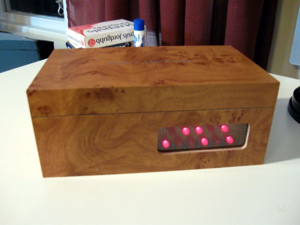
This Instructable will show you how to build an binary alarm clock, with a touch sensor snooze button. This is my first instructable and my first real arduino project, I hope you like it!
I bought an arduino a while back and I think it’s really nice, but I haven’t really done anything useful with it yet, so now I thought it was time to make a bigger project. I decided to do an alarm clock since my old one is broken.
There seems to be some problems with the video embedding, If you can’t see the video above, here’s a link to it: binary alarm clock
Step 1: What should be done?
To help me organize my thoughts about how I should build the clock I wrote down what I think an alarm clock should be able to do. I then tried to build the clock to meet the requirements.
An alarm clock should be able to: What I used:
– keep time – code
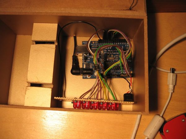
– display time – LEDs 5 for hours, 6 for minutes
– keep an alarm time – code
– let the user set the time – buttons
– let the user set the alarm – buttons
– make noise when the alarm goes off. – speaker
– let the user snooze – touch sensor “button”
– let the user turn on and off the alarm. – touch sensor “button”
It would be nice if it also:
– looks reasonably good – a nice box as case
– is cool and geeky – true binary display
Step 2: What you need.
Parts:
For the display:
– 11 LEDs
– 11 1kΩ resistors ( don’t need to be exact, anything between 300 and 2k should work (a lower value will give brighter light)
– Perfboard (I used perfboard with separate solderpads for each hole)
For sound:
– 1 Speaker (piezo or ordinary, if you use an ordinary speaker put a 1kΩ resistor in series with it)
For time and alarm setting:
– 2 Buttons (Hour button and Minute button).
– 1 Switch for changing between setting the time and setting the alarm.
– A piece of thin plywood.
For the touch sensor:
– Aluminum foil, or even better aluminum tape.
– Tape or glue to attach the foil.
– Paper in the same color as the box to hide the sensor
– Glue for the paper.
– 1MΩ resistor (you can play with this value a bit, depending on how thick your box is, a higher
value gives a more sensitive sensor (it will also make it a bit slower).
For everything:
– Hookup wire (solid core wire)
– Electrical tape
– Solder
– A box to put everything in.
Tools:
– A soldering iron
– Wirecutter and wirestripper
– Drill, or something else to make holes in the case for buttons.
– Saw
Not a must, but good to have:
– A multimeter, for testing connections, etc.
– A solderless breadboard can be good to have to be able to test stuff easily.
– Header pins for connecting the wires to the arduino. I didn’t have this and had some problems at first with getting good contact in the connections to the arduino at first, I solved it by securing the connections with tape.
Step 3: Code Structure
I have divided the code for the clock into functions, one for each important bit of functionality. The functions are in separate tabs in the sketch. these are then run in the main loop:
void loop()
{
clock(); // keep track of time, i.e. update hours, minutes and seconds variables as needed.
display(); // display the time, or the alarm time, depending on the state of the settings switch.
alarm(); // checks if it’s time for the alarm to start.
update_buttons_state(); // checks if the buttons and touch sensor states has changed
buttons(); // does what the buttons should do
}
The variables that are needed by several functions are declared in the first tab (where setup() and loop() is) and the variables that are needed only by one function is declared in the same tab as that function.
If you change the DEBUG constant to 1 you will get some output via serial that can be good for troubleshooting, e.g. the time and what value the touchsensor returns.
I have tried to comment and make the code understandable but if you have questions or suggestions for improvements just leave a comment.
– 11 LEDs
– 11 1kΩ resistors
– Perfboard
For sound:
– 1 Speaker
For time and alarm setting:
– 2 Buttons
For more detail: Arduino Binary Alarm Clock