Summary of Arduino-Based Robotic Arm Controlled by Hand Gestures
Summary (under 100 words): This article describes a hand-gesture controlled robot arm using an Arduino UNO, four upward-facing IR sensors, and two servo motors. IR sensors detect hand presence and send signals to Arduino which drives two servos for X and Y motion. Construction uses cardboard for mounting, jumper wires/breadboard for connections, and provided Arduino code (requires Servo.h). Pin mappings and wiring instructions are included for sensors and servos.
Parts used in the Hand Gesture Controlled Robot Arm:
- Arduino UNO
- 4 infrared (IR) sensors
- 2 servo motors
- Cardboard pieces
- Jumper wires
- Breadboard
- USB cable for uploading code
Introduction
Greetings to all, hoping everyone is in good health. We’re thrilled to present our newest article about Arduino projects. This article discusses the development of a robot arm that is operated through hand movements with the help of Arduino UNO. To identify hand motions, we will use four IR sensors placed in four separate orientations with their sensor heads pointed up. Feel at liberty to discover more Arduino and IoT projects created by our team. Adhere to the circuit diagram to put together the parts and then upload the given code to the Arduino board.
Description
In this project, the movement of the robot arm is manipulated without any physical touch. On the contrary, it reacts to hand movements by employing IR sensors embedded in the system. These sensors identify hand motions and produce a strong signal when they sense obstacles nearby.
Two servo motors control the movements along the x-axis and y-axis, respectively. When you place your hand above the sensors, the robotic arm changes its movement in response. These robotic arms are currently in high demand, being used in a wide range of industries to increase efficiency.
Thoroughly examine the article for detailed guidance on constructing this project on your own. Moreover, you have the option to investigate our previously developed WiFi controlled robot with nodemcu for more information.
Components Required
Certainly, here’s a rephrased list of the components required:
– Arduino UNO
– 4 infrared (IR) sensors
– 2 servo motors
– Cardboard pieces
– Jumper wires and a breadboard
– USB cable used for uploading the code
Circuit For Hand Gesture Controlled Robot
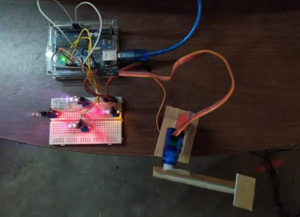
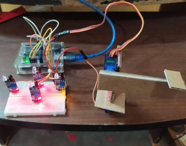
Start by placing two servo motors one on top of the other as shown in the provided project image. Use a cardboard piece to hold up this arrangement.
After that, connect the positive supply cables of the two servo motors to the 5-volt pin on the Arduino. Attach the servos’ negative supply wires to the Arduino’s GND pin.
Continue by connecting the signal wire of the initial servo motor to the digital-12 pin on the Arduino. Attach the second servo motor’s signal wire to the Arduino’s digital-13 pin.
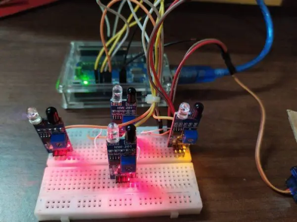
Next, obtain four IR sensors and wire their VCC pins to the 5-volt pin on the Arduino. Join the ground pins of these sensors to the ground pin of the Arduino.
Use a breadboard for efficient connections. Connect the OUT pin of the initial, second, third, and fourth IR sensors to the digital-8, digital-6, digital-7, and digital-9 pins of the Arduino correspondingly. Your circuit has been put together and is prepared for utilization.
Code For Hand Gesture Controlled Robot
Attention: Prior to uploading this code to the Arduino, ensure the installation of <Servo.h> in case an error occurs. You can refer to instructions on adding a zip library to the Arduino IDE here for guidance.
//Techatronic.com
#include
Servo motor1;
Servo motor2;
int sensor1 = 8;
int sensor2 = 6;
int sensor3 = 7;
int sensor4 = 9;
void setup() {
pinMode(sensor1,INPUT);
pinMode(sensor2,INPUT);
motor1.attach(12);
motor2.attach(13);
// Serial.begin(9600);
}
void loop() {
int top = digitalRead(sensor1);
int bottom = digitalRead(sensor2);
int right = digitalRead(sensor3);
int left = digitalRead(sensor4);
//Serial.println(top);
//Serial.println(bottom);
//Serial.println(right);
//Serial.println(left);
if (top == 1 && bottom == 1 && right == 1 && left == 1)
{
motor1.write(60);
motor2.write(60);
}
else if(top == 1 && bottom == 1 && right == 1 && left == 0)
{
motor1.write(0);
motor2.write(60);
}
else if(top == 1 && bottom == 1 && right == 0 && left == 1)
{
motor1.write(180);
motor2.write(60);
}
else if(top == 1 && bottom == 1 && right == 0 && left == 0)
{
motor1.write(60);
motor2.write(60);
}
else if(top == 1 && bottom == 0 && right == 1 && left == 1)
{
motor1.write(60);
motor2.write(0);
}
else if(top == 1 && bottom == 0 && right == 1 && left == 0)
{
motor1.write(0);
motor2.write(0);
}
else if(top == 1 && bottom == 0 && right == 0 && left == 1)
{
motor1.write(180);
motor2.write(0);
}
else if(top == 1 && bottom == 0 && right == 0 && left == 0)
{
motor1.write(60);
motor2.write(0);
}
else if(top == 0 && bottom == 1 && right == 1 && left == 1)
{
motor1.write(60);
motor2.write(180);
}
else if(top == 0 && bottom == 1 && right == 1 && left == 0)
{
motor1.write(0);
motor2.write(180);
}
else if(top == 0 && bottom == 1 && right == 0 && left == 1)
{
motor1.write(180);
motor2.write(180);
}
else if(top == 0 && bottom == 1 && right == 0 && left == 0)
{
motor1.write(60);
motor2.write(180);
}
else if(top == 0 && bottom == 0 && right == 1 && left == 1)
{
motor1.write(60);
motor2.write(60);
}
else if(top == 0 && bottom == 0 && right == 1 && left == 0)
{
motor1.write(0);
motor2.write(60);
}
else if(top == 0 && bottom == 0 && right == 0 && left == 1)
{
motor1.write(180);
motor2.write(60);
}
else if(top == 0 && bottom == 0 && right == 0 && left == 0)
{
motor1.write(0);
motor2.write(0);
}
}
We hope you found this project enjoyable and have a good understanding of its concepts. If you have any questions or doubts about this project, please make use of the comments section provided. Furthermore, delve into additional guides on Arduino and Raspberry Pi to enhance your learning experience.
- What microcontroller is used in the project?
The project uses an Arduino UNO as the microcontroller. - How many IR sensors are required?
The project requires four IR sensors placed in four orientations with heads pointed up. - Which pins are the servo signal wires connected to?
The first servo signal is connected to digital pin 12 and the second servo signal to digital pin 13. - Which Arduino pins do the IR sensor OUT pins connect to?
The IR sensor OUT pins connect to digital pins 8, 6, 7, and 9 respectively. - What power connections are needed for servos and sensors?
Connect the servos and IR sensors VCC pins to the Arduino 5V pin and all grounds to the Arduino GND pin. - What library must be installed before uploading the code?
You must install Servo.h in the Arduino IDE before uploading the code. - How are the two servos mechanically arranged?
The two servo motors are mounted one on top of the other and supported by a cardboard piece as shown in the project image. - Does the project require physical touch to operate?
No, the robot arm is operated without physical touch and responds to hand movements detected by IR sensors. - Is a breadboard used in the circuit?
Yes, a breadboard is recommended for efficient connections. - Where can you find the upload cable connection?
A USB cable is used to upload the code to the Arduino.