In this tutorial, we’re going to make a simple data logger using Arduino. The point is to learn the very basics of using Arduino to capture information and print to the terminal. We can use this basic setup to complete a range of tasks.
To get started:
You will need a Tinkercad (www.tinkercad.com) account. Head over and sign up with your email or social media account.
Logging in takes you to the Tinkercad Dashboard. Click “Circuits” to the left and select “Create new Circuit”. Let’s get started!
You can find the complete file on TInkercad Circuits – Thanks for checking it out!
Step 1: Add Some Components
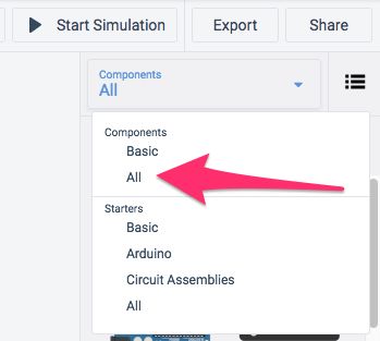
You’ll need some basic components. These include:
- Arduino board
- Breadboard
Add those by searching for them and click-dragging them to the middle area.
Place the breadboard over the Arduino. It makes it easier to view the connections later.
Step 2: A Note About Breadboards
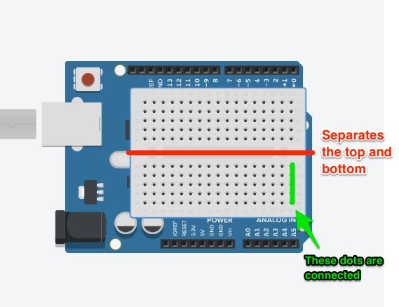
A breadboard is a super helpful device for rapid prototyping. We use it to connect components. Some things to note.
- The dots are connected vertically, but the line in the middle separates this connection from the top and bottom columns.
- Columns are not connected left to right, as in across the row. This means that all components should be connected across the columns rather than down them vertically.
- If you need to use buttons or switches, connect them across the break in the middle. We’ll visit this in a later tutorial.
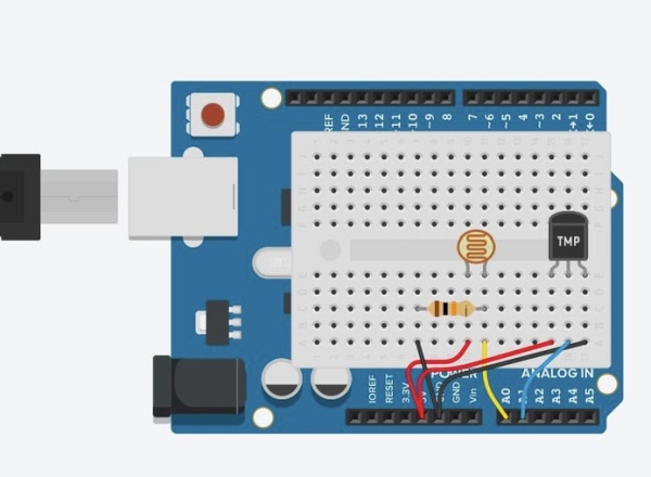
Step 3: Add Two Sensors
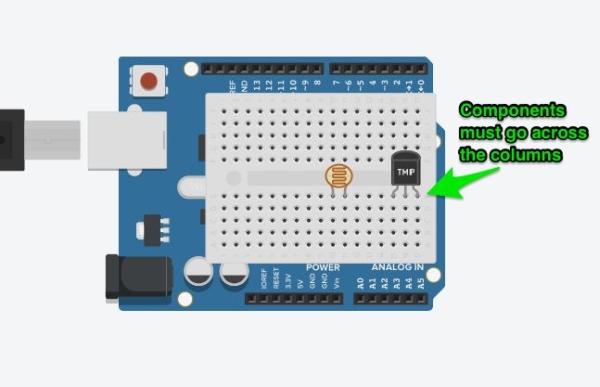
The two sensors we are using are a Photosensitive sensor and Temperature sensor.
These sensors evaluate light and temperature. We use Arduino to read the value and display it in the Serial monitor on the Arduino.
Search for and add the two sensors. Make sure they are positioned across the columns on the breadboard. Put enough space between them to make it easier to see them.
Step 4: Photosensitive Sensor
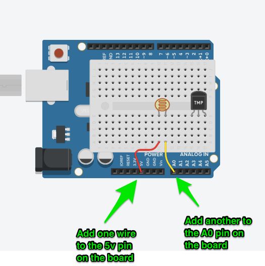
- For the photosensitive sensor, add a wire from the 5V pin on the Arduino to the same column as the right leg on the part in the breadboard. Change the wire colour to red.
- Connect the left leg via the pin in the same column to the A0 (A-zero) pin on the Arduino. This is the analog pin, which we will use to read the value from the sensor. Colour this wire yellow or something other than red or black.
- Place a resistor (search and click-drag) on the board. This completes the circuit and protects the sensor and pin.
- Turn it around so it goes across the columns.
- Connect one leg to the right leg column on the breadboard
- Place a wire from the other end of the resistor to the ground
- Change the wire colour to black.
- Double check all connections. If something isn’t in the right place, this won’t function correctly.
Source: Arduino Datalogger