Summary of ARDUINO BASED MILLIOHM METER WITH LCD DISPLAY
This article details a DIY milliohm meter project by danielrp, designed to measure low resistances with high precision. The device utilizes an Arduino Nano, an LT3092 precision current sink, and an MCP3422A0 18-bit ADC. It features three selectable measurement scales, Kelvin connectors to minimize lead resistance errors, and a 16×2 LCD for visual feedback, all housed in a Hammond 1590B aluminum enclosure.
Parts used in the Arduino Based Milliohm Meter:
- Arduino Nano
- LT3092 precision current source/sink
- MCP3422A0 I2C ADC
- Kelvin connectors
- Push buttons (two)
- 16×2 LCD display
- Hammond 1590B aluminum box
One of the best things about being a maker is the ability to make your own tools. We have covered the development of several electronics tools in past, from voltmeters to battery testers. For today’s tutorial, we will add another tool to the list by examining the development of a Miliohm meter made by danielrp @ www.instructables.com
A milliohm meter is a device used in determining the resistance of small resistors, PCB traces, motor coils, inductance coils, and transformer coils, or calculate things like the length of wires. It provides a resolution, not built into regular multimeters, making it easy to get accurate readings in the milliohm range.
There are quite a number of Miliohmeter builds on the internet, but today’s tutorial will chronicle the efforts of instructable user Danielrp. Daniel’s version of the meter is based on a precision current sink and a high-resolution ADC controlled by an Arduino Nano. The current sink is based on the LT3092 precision current source/sink which, using a network of resistors and transistors is set to function as a sink. For the ADC, the high resolution, MCP3422A0 I2C ADC is used. Just one of the channels of the ADC is used, and it is connected differentially to the Resistor under test “S+ S-“. The MCP3422 is configured as 18bit but as S+ is always going to be greater than S-, the effective resolution is 17bit.
To reduce the influence of the resistance of the test leads on the measurement, the devices use Kelvin connectors as leads to connect the resistor under test to the measurement point.
The measurement range of the device include:
- Scale 0m1: 0.1mOhm to 12.9999 Ohm.
- Scale 1m0: 1mOhm to 129.999 Ohm.
- Scale 10m: 10mOhm to 1299.99 Ohm.
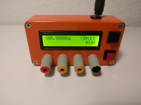
Users can make the selection between the above measurement ranges by using one of the two push buttons on the device. Visual feedback on the selections and meter readings is provided to users via a 16×2 LCD display, and the entire project is enclosed in an orange Hammond 1590B aluminum box to make it handy and presentable.
Ready to build? let’s dive in.
REQUIRED COMPONENTS
Due to the bulkiness, the complete list of components required to build the project is attached under the download section. However, some of the key components to be used include:
Read more: ARDUINO BASED MILLIOHM METER WITH LCD DISPLAY
- What is the primary function of this device?
It determines the resistance of small resistors, PCB traces, motor coils, inductance coils, transformer coils, or calculates wire length. - How does the device handle lead resistance influence?
The devices use Kelvin connectors as leads to connect the resistor under test to the measurement point. - Which microcontroller controls the ADC in this build?
An Arduino Nano controls the high-resolution ADC. - What is the effective resolution of the ADC when S+ is greater than S-?
The effective resolution is 17bit even though the MCP3422 is configured as 18bit. - How many measurement scales are available on the device?
There are three measurement ranges: Scale 0m1, Scale 1m0, and Scale 10m. - How do users select between the different measurement ranges?
Users make the selection using one of the two push buttons on the device. - What type of enclosure is used for the project?
The entire project is enclosed in an orange Hammond 1590B aluminum box. - What component provides the precision current sink for the measurement?
The LT3092 precision current source/sink is used as the current sink.