Summary of Arduino – based camera trigger unit
This article details an Arduino-based camera trigger unit designed to synchronize high-speed cameras and LED indicators with electrical stimuli delivered to hawkmoths during wind tunnel experiments. The system supports manual or laser-activated triggering, utilizing phototransistor sensors to detect objects crossing laser beams. It manages a precise timing sequence: initiating stimulus transmission, lighting LEDs, and finally triggering the cameras to capture pre- and post-event footage.
Parts used in the Camera Trigger Unit:
- Arduino Diecimila microcontroller board
- Red or infrared laser diodes (one or two)
- Phototransistor-based sensors
- LED indicators
- Miniature stimulus chip for hawkmoth
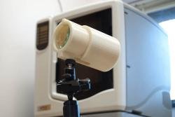
- Phantom high-speed cameras
- USB serial communication interface
- Manual trigger buttons (Button A and Button B)
I developed the camera trigger unit in order to synchronize various events and actions during free-flight experiments with hawkmoths in the wind tunnel described in a previous post. More specifically, the goal was to trigger multiple high-speed cameras and have LEDs that indicate the exact timing of electrical stimuli delivered via a miniature stimulus chip carried by a hawkmoth. (Electric stimulation of the moth is also triggered by the unit.)
The trigger is based on an Arduino micro-controller board (http://www.arduino.cc/) and provides a timed sequence of events after a trigger is elicited either manually, or automatically with the optional laser module. The latter is used to monitor a volume in space (the trigger volume) that, when occupied by an object (a moth, for example), elicits the trigger sequence. The module can be used with one or two red or infrared laser diodes. When using one laser beam, an object crossing anywhere along the beam will elicit a trigger event. When using two beams, the volume in space in which the two beams cross defines the trigger volume.
Timing of events
Phantom high-speed cameras (as well as many other high-speed camera models) are continuously recording image data into their internal buffer memory until a trigger event input is set high. To make sure a stimulus event is recorded by all cameras, a single “Trigger event” (red letters, top left) initiates the sequence illustrated in the figure above. The circuit immediately communicates with the transmitter for the chip on board the flying moth. From this time point on, it takes 84 ms until the on-board chip sends out its pre-programmed electric stimulus train (signal 1). Thus, another voltage output (2) is timed to coincide with the on-board stimulus to illuminate a set of LED indicators, at least one of which is visible in all cameras. This means that moth stimulation coincides with the onset of the LEDs.
After a definable amount of post-stimulus time, a camera trigger signal (3) switches the “trigger event” input of the high-speed cameras. This stops the recording and leaves the last few seconds of video on the cameras’ internal buffer. The settings on the camera determine how many post-trigger frames are saved, which in turn determines the maximum number of pre-trigger frames (npre) for a given memory size. In addition to the signals discussed in the above figure, the unit also produces an audible alarm when a trigger event occurs.
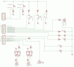
Arduino software
The main work of the circuit is performed by an Arduino (Diecimila) microcontroller board that I programmed in the Arduino programming language (similar to C). The microcontroller monitors several of its digital inputs to react when buttons are pressed, and to measure the light levels falling on two phototransistor-based sensors. It also performs the logic for sending out signals when certain conditions are met (e.g. button A is pressed, sensors A and B are below threshold, etc.).
The program is organized into three main loops, which correspond to different system states:
When the trigger unit is powered up, the program starts out in Idle mode, which is indicated by a green LED on the front panel. Pressing button A while in Idle mode leads the program to enter Armed status, in which lasers are turned on, and data acquisition on the two sensor channels is started. While in this loop (indicated by the red LED on the front panel) the microcontroller waits for both sensor levels to fall simultaneously, which happens when an object occupies the volume in which both beams cross. If this occurs, or button B is pressed as a manual trigger, the trigger function is called. This function leads to the timed sequence of events discussed above.
The Alignment mode is used during initial setup of the unit to help line up the laser beams with their respective sensor targets. The Alignment routine is initiated by pressing button B longer than one second during Idle mode. When in Alignment mode, both Idle and Armed indicator LEDs light up on the front panels, and both lasers are powered up. Additionally, the Arduino’s USB serial communication is opened and sends the sensor values to a host computer at a Baud rate of 9600 bits/s. These values can easily be displayed with the serial monitor in the Arduino IDE. The goal is to maximize the light level (value of 1023) on each sensor by adjusting laser and sensor positions. Blocking the intersection of the laser beams with a mock target object leads to lower sensor readings. These lower readings should be noted and used as new threshold values in the code. After re-compiling and re-uploading the adjusted program via the USB connection, the laser trigger unit will be operational.
For more detail: Arduino – based camera trigger unit
- How does the laser module trigger the sequence?
An object crossing one beam triggers immediately, while two crossing beams define a specific volume where simultaneous occupation elicits the trigger. - What is the delay between the trigger event and the moth's electric stimulus?
It takes 84 ms from the trigger event for the on-board chip to send its pre-programmed electric stimulus train. - Can I manually activate the trigger unit?
Yes, pressing button B while in Armed status acts as a manual trigger to start the timed sequence. - How do I align the laser beams with the sensors?
Enter Alignment mode by holding button B for over one second in Idle mode, then adjust positions until sensor values reach 1023. - Does the unit produce an audible signal when triggered?
Yes, the unit generates an audible alarm whenever a trigger event occurs. - What happens to the camera recording after the trigger signal?
The camera stops recording and saves the last few seconds of video stored in its internal buffer memory. - How is the threshold value determined for the laser trigger?
Users block the laser intersection with a mock target, note the resulting lower sensor reading, and update the code with this new value.